

0
Owner's of the Agilent Technologies Video Gaming Accessories Agilent Technologies Video Gaming Accessories gave it a score of 0 out of 5. Here's how the scores stacked up:


Chapter 4 Theory of Operation
Earth-Referenced Logic
88
Earth-Referenced Logic
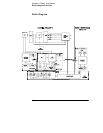
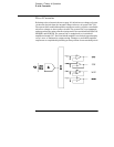
Referring to the schematic shown on page 125, the earth referenced logic
circuits schematic provides all rear panel input/output capability.
Microprocessor U4 handles GPIB (IEEE-488) control through bus interface
chip U3 and bus receiver/driver chips U1 and U2. The RS-232 interface is also
controlled through microprocessor U4. RS-232 transceiver chip U17 provides
the required level shifting to approximate
±9 volt logic levels through on-chip
charge-pump power supplies using C5 and C15. Communication between the
earth referenced logic interface circuits and the floating logic is accomplished
through an optically-isolated bi-directional serial interface. Isolator U7 couples
data from U4 to processor U17. Isolator U6 couples data from U17 to
microprocessor U4.
Front Panel
Referring to the schematic shown on page 127, the front panel circuits consist
of vacuum fluorescent display control, display high voltage drivers, and
keyboard scanning. Communication between the front panel and floating logic
circuits is accomplished through a 4-wire bi-directional serial interface. The
main controller U17 can cause a hardware reset to front-panel controller by
signal IGFPRES. The front panel logic operates from -12.4 volts (logic 1) and -
17.4 volts (logic 0). The front panel logic high supply (-12.4 volts) is produced
by the -17.4 volts bias supply and the voltage regulator U2 on the front panel
board. The four serial communication signals are level shifted by the
comparator U8 from the floating logic 0 V to 5 V levels to the -17.4 V to -12.4 V
levels present on the front panel assembly. U6 acts as the serial shift register
interface for the front-panel controller U7 on the front panel board.
Display anode and grid voltages are +17.4 volts for an "on" segment and -17.4
volts for an "off" segment. The -11.2 V cathode bias for the display is provided
by filament winding center tap bias circuit VR1, R18, and C25 on the main
board. Keyboard scanning is accomplished through a conventional scanned
row-column key matrix. Keys are scanned by outputing data at front-panel
controller U7 port pins P0.0 through P0.3 to poll each key column for a key
press. Column read-back data are read by the microprocessor at port pins P1.0
through P1.3 for decoding and communication to the floating logic circuits.


Find Your Products By Category
- Household Appliance
- Power Tools
- Computer Equipment
- Automotive
- TV and Video
- Outdoor Cooking
- Marine Equipment
- Kitchen Appliance
- Fitness & Sports
- Lawn and Garden
- Baby
- Laundry Appliance
- Personal Care
- Home Audio
- Photography
- Video Game
- Portable Media
- Musical Instruments & Equipment
- Communications
- Car Audio and Video
Please Login
