
0
Owner's of the Agilent Technologies Video Gaming Accessories Agilent Technologies Video Gaming Accessories gave it a score of 0 out of 5. Here's how the scores stacked up:

Chapter 3 Calibration Procedures
Constant Voltage (CV) Verifications
51
3
2
Connect the ac power line through a variable voltage transformer.
3
Turn on the power supply. Select the 30V/4A range, enable the output, and set
the display to the limit mode. When the display is in the limit mode, program
the current to the full rated value (4.0A) and the voltage to full rated value
(30.0V).
4
Operate the electronic load in constant current mode and set its current to
4.0A. Check that the
CV annunciator remains lit. If not lit, adjust the load so
that the output current drops slightly until the
CV annunciator lights.
5
Adjust the transformer to low line voltage limit (104 Vac for nominal 115 Vac,
90 Vac for nominal 100 Vac, or 207 Vac for nominal 230 Vac). Record the output
reading on the digital voltmeter.
6
Adjust the autotranformer to high line voltage (127 Vac for nominal 115 Vac,
110 Vac for nominal 100 Vac, or 253 Vac for nominal 230 Vac). Record the
voltage reading on the digital voltmeter. The difference between the digital
voltmeter readings in steps (5) and (6) is the CV line regulation. The difference
of the readings should be within the limit of 5mV.
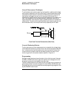
Normal Mode Voltage Noise (CV Ripple and Noise)
The normal mode voltage noise is in the form of ripple related to the line
frequency plus some random noise. The normal mode voltage noise is specified
as the rms or peak-to-peak output voltage in a frequency range from 20 Hz to
20 MHz.
1
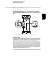
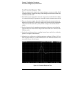
Turn off the power supply and connect the output to be tested as shown in Figure
3-1 to an oscilloscope (ac coupled) between (+) and (-) terminals. Set the
oscilloscope to AC mode and bandwidth limit to 20 MHz. Connect a resistive
load (7.5
W
) as shown in Figure 3-1.
2
Turn on the power supply. Select the 30V/4A range, enable the output, and set
the display to the limit mode. When the display is in the limit mode, program
the current to the full rated value (4.0A) and the voltage to the full rated value
(30.0V).
3
Check that the front panel
CV annunciator remains lit. If not lit, adjust the load
down slightly.
4
Note that the waveform on the oscilloscope does not exceed the peak-to-peak
limit of 2 mV.
5
Disconnect the oscilloscope and connect an AC rms voltmeter in its place. The
rms voltage reading does not exceed the rms limit of 0.35 mV.


Find Your Products By Category
- Household Appliance
- Power Tools
- Computer Equipment
- Automotive
- TV and Video
- Outdoor Cooking
- Marine Equipment
- Kitchen Appliance
- Fitness & Sports
- Lawn and Garden
- Baby
- Laundry Appliance
- Personal Care
- Home Audio
- Photography
- Video Game
- Portable Media
- Musical Instruments & Equipment
- Communications
- Car Audio and Video
Please Login
