
0
Owner's of the Agilent Technologies Video Gaming Accessories Agilent Technologies Video Gaming Accessories gave it a score of 0 out of 5. Here's how the scores stacked up:

Chapter 3 Calibration Procedures
Constant Current (CC) Verifications
55
3
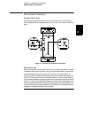
CC Line Regulation
This test measures the change in output current that results from a change in
ac line voltage from the minimum value (10% below the nominal input voltage)
to the maximum value (10% above nominal voltage).
1
Turn off the power supply and connect the output to be tested as shown in Figure
3-1 with the digital voltmeter connected across the current monitoring resistor
(R
M
).
2
Connect the ac power line through a variable voltage transformer.
3
Turn on the power supply. Select the 15V/7A range, enable the output, and set
the display to the limit mode. When the display is in the limit mode, program
the voltage to the full rated value (15.0V) and the current to the full rated value
(7.0A).
4
Operate the electronic load in constant voltage mode and set its voltage to
15.0V. Check that the
CC annunciator remains lit. If not lit, adjust the load so
that the output voltage drops slightly until the
CC annunciator lights.
5
Adjust the transformer to low line voltage limit (104 Vac for nominal 115 Vac,
90 Vac for nominal 100 Vac, or 207 Vac for nominal 230 Vac). Record the output
current reading by dividing the voltage reading on the digital voltmeter by the
resistance of the current monitoring resistor.
6
Adjust the transformer to 10% above the nominal line voltage (127 Vac for a
115 Vac nominal input, 110 Vac for a 100 Vac nominal input or 253 Vac for a
230 Vac nominal input). Record the current reading again by dividing the
voltage reading on the digital voltmeter by the resistance of the current
monitoring resistor. The difference between the current readings in step (5)
and (6) is the load regulation current. The difference of the readings should be
within the limit of 0.95mA.
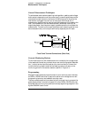
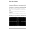
Normal Mode Current Noise (CC Ripple and Noise)
The normal mode current noise is specified as the rms output current in a
frequency range 20 Hz to 20 MHz with the power supply in constant current
operation.
1
Turn off the power supply and connect the output to be tested as shown in Figure
3-1 with a load resistor (2.1
9
) across output terminals to be tested. Connect a
rms voltmeter across the load resistor. Use only a resistive load for this test.


Find Your Products By Category
- Household Appliance
- Power Tools
- Computer Equipment
- Automotive
- TV and Video
- Outdoor Cooking
- Marine Equipment
- Kitchen Appliance
- Fitness & Sports
- Lawn and Garden
- Baby
- Laundry Appliance
- Personal Care
- Home Audio
- Photography
- Video Game
- Portable Media
- Musical Instruments & Equipment
- Communications
- Car Audio and Video
Please Login
