
0
Owner's of the Agilent Technologies Power Supply Agilent Technologies Power Supply gave it a score of 0 out of 5. Here's how the scores stacked up:
1-8
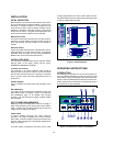
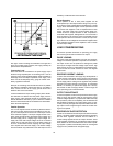
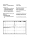
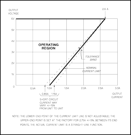
Figure 3. Current Limit Characteristic of the 6V Supply
this region. If the line voltage is maintained in the upper end
of the input voltage range, however, the supply probably will
operate within its specifications
Connecting Load
Each load should be connected to the power supply output
terminals using separate pairs of connecting wires. This will
minimize mutual coupling effects between loads and takes full
advantage of the low output impedance of the supply. Load
wires must be of adequately heavy gauge to maintain satis-
factory regulation at the load.
Each pair of connecting wires should be as short as possible
and twisted or shielded to reduce noise pick-up. If a shield is
used, connect one end to the supply ground terminal and
leave the other end unconnected.
If load considerations require locating output power distribu-
tion terminals at a distance from the power supply, then the
power supply output terminals should be connected to the
remote distribution terminals by a pair of twisted or shielded
wires and each load should be connected to the remote distri-
bution terminals separately.
Parallel Operation
Two or more supplies can be connected in parallel to obtain a
total output current greater than that available from one sup-
ply. The total output current is the sum of the output currents
of the individual supplies. The output voltage controls of one
power supply should be set to the desired output voltage, and
the other supply set for a slightly larger output voltage. The
supply set to the lower output voltage will act as a constant
voltage source, while the supply set to the higher output will
act as a current-limited source, dropping its output voltage
until it equals that of the other supply. The constant voltage
source will deliver only that fraction of its rated output current
necessary to fulfill the total current demand.
Series Operation
Series operation of two or more power supplies can be
accomplished up to the output isolation rating of any one sup-
ply to obtain a higher voltage than that available from a single
supply. Series connected supplies can be operated with one
load across both supplies or with a separate load for each
supply. The power supply has a reverse polarity diode con-
nected across the output terminals so that if operated in
series with other supplies, damage will not occur if the load is
short-circuited or if one supply is turned on separately from its
series partners. When this connection is used, the output volt-
age is the sum of the voltages of the individual supplies. Each
of the individual supplies must be adjusted in order to obtain
the total output voltage.
LOAD CONSIDERATIONS
This section provides information on operating your supply
with various types of loads connected to its output.
PULSE LOADING
The power supply will automatically cross over from constant-
voltage to current-limit operation in response to an increase in
the output current over the preset limit. Although the preset
limit may be set higher than the average output current, high
peak currents (as occur in pulse loading) may exceed the pre-
set current limit and cause crossover to occur and degrade
performance.
REVERSE CURRENT LOADING
An active load connected to the supply may actually deliver a
reverse current to the supply during a portion of its operating
cycle. An external source can not be allowed to pump current
into the supply without risking loss of regulation and possible
damage to the output capacitor of the supply. To avoid these
effects, it is necessary to preload the supply with a dummy
load resistor so that the supply delivers current through the
entire operating cycle of the load devices.
OUTPUT CAPACITANCE
An internal capacitor across the output terminals of the supply
helps to supply high-current pulses of short duration during
constant-voltage operation. Any capacitance added externally
will improve the pulse current capability, but will decrease the
load protection provided by the current limiting circuit. A high-
current pulse may damage load components before the aver-
age output current is large enough to cause the current limit-
ing circuit to operate.
REVERSE VOLTAGE PROTECTION
A diode is connected across the output terminals with reverse
polarity. This diode protects the output electrolytic capacitors
and the series regulator transistors from the effects of a
reverse voltage applied across the output terminals. Since
series regulator transistors can not withstand reverse voltage
either, diodes are also connected across them. When operat-
ing supplies in parallel, these diodes protect an unenergized
supply that is in parallel with an energized supply.


Find Your Products By Category
- Household Appliance
- Power Tools
- Computer Equipment
- Automotive
- TV and Video
- Outdoor Cooking
- Marine Equipment
- Kitchen Appliance
- Fitness & Sports
- Lawn and Garden
- Baby
- Laundry Appliance
- Personal Care
- Home Audio
- Photography
- Video Game
- Portable Media
- Musical Instruments & Equipment
- Communications
- Car Audio and Video
Please Login
