
0
Owner's of the Agilent Technologies Power Supply Agilent Technologies Power Supply gave it a score of 0 out of 5. Here's how the scores stacked up:
A-10
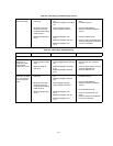
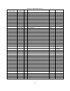
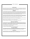
Table A-7. +6V Supply Troubleshooting
SYMPTOM STEP - ACTION RESPONSE PROBABLE CAUSE
The +20V supply must operate properly before troubleshooting the -20V supply.
High output voltage
(higher than rating)
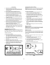
1. Attempt to turn off Q1 by
shorting emitter-to-base
of Q1.
2. Measure voltage at
base of Q4.
a. Output voltage remains high.
b. Output voltage becomes near zero
volt.
a. Measured voltage is more than
-0.6V.
b. Measured voltage is less than
-0.6V.
a. Q1 shorted.
b. Remove short and proceed to
step 2.
a. Check for defective Q4.
b. Check for open CR6, R11 and
check for defective U2A.
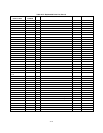
Low output voltage
(lower than rating)
1. Measure voltage at the
base of Q4.
2. Eliminate current limit
circuit as a source of
trouble by disconnecting
anode of CR7.
3. Measure voltage at
pin 3 of U2.
a. Measured voltage is less than
-0.6V.
b. Measured voltage is more than
-0.6V.
a. Output voltage increases.
b. Output voltage remains low.
a. Measured voltage is near
-0.7V.
b. Measured voltage is zero volt.
c. Measured voltage is near
+0.7V.
a. Check for open Q1, Q6, R25, or
CR5.
b. Proceed to step (2).
a. Check for U2B defective.
b. Reconnect lead and proceed to
step (3).
a. Check for defective U2A.
b. Check for CR9 and CR10 shorted.
c. Check for open R29, shorted R11,
or leaky or shorted C5.
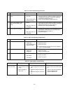
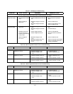
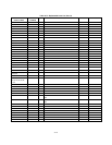
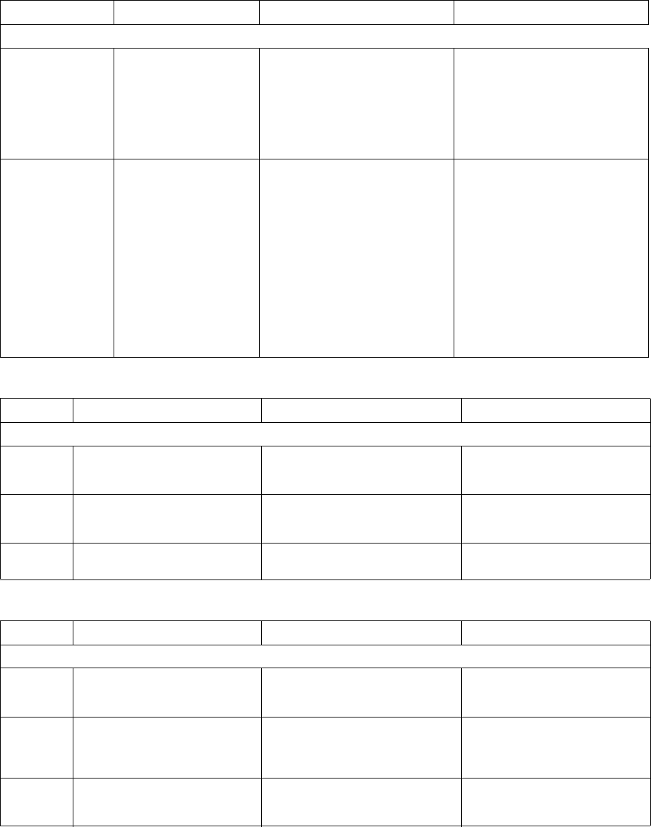
Table A-8. +20V Preregulator/Control Circuit Troubleshooting
STEP ACTION RESPONSE PROBABLE CAUSE
Set output voltage at 12V+0.5V.
1 Measure pin 1 of U14. a. Measured voltage is -12V.
b. Measured voltage is near
+4.3V.
a. Proceed to step (2).
b. Check for defective U14A.
2 Measure pin 1 of U13. a. Measured voltage is near +1V
b. Measured voltage is near 0V.
a. Check for defective U13 or
CR12.
b. Check for open Q11 or R81.
3 Measure pin 1 of U11. a. Measured voltage is near +1V
b. Measured voltage is near 0V.
a. Check for defective U11.
b. Check for open Q11 or R82.
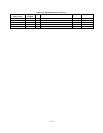
Table A-9. -20V Preregulator/Control Circuit Troubleshooting
STEP ACTION RESPONSE PROBABLE CAUSE
Set output voltage at -12V-0.5V.
1 Measure pin 7 of U14. a. Measured voltage is -12V.
b. Measured voltage is near
+4.3V.
a. Proceed to step (2).
b. Check for defective U14B.
2 Measure pin 1 of U12. a. Measured voltage is near +1V
b. Measured voltage is near
+4.3V.
a. Check for defective U12 or
CR31.
b. Check for open Q10 or R56
3 Measure pin 1 of U10. a. Measured voltage is near +1V
b. Measured voltage is near 0V.
a. Check for defective U10 or
CR27.
b. Check for open Q10 or R55.


Find Your Products By Category
- Household Appliance
- Power Tools
- Computer Equipment
- Automotive
- TV and Video
- Outdoor Cooking
- Marine Equipment
- Kitchen Appliance
- Fitness & Sports
- Lawn and Garden
- Baby
- Laundry Appliance
- Personal Care
- Home Audio
- Photography
- Video Game
- Portable Media
- Musical Instruments & Equipment
- Communications
- Car Audio and Video
Please Login
