
0
Owner's of the Agilent Technologies Power Supply Agilent Technologies Power Supply gave it a score of 0 out of 5. Here's how the scores stacked up:
A-3
Operation Verification Tests
The followin
g
tests assure that the power suppl
y
is per-
formin
g
properl
y
. The
y
do not, however, check all the speci-
fied parameters tested in the complete performance test
described below. Proceed as follows:
a. Perform turn-on checkout procedure
g
iven in pa
g
e 1-7.
b. Perform the load re
g
ulation performance tests
g
iven in
the followin
g
para
g
raphs.
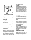
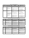
Line Volta
g
e Option Conversion
To convert the suppl
y
from one line volta
g
e option to another,
the followin
g
three steps are necessar
y
:
a. After makin
g
certain that the line cord is disconnected
from a source of power, remove the top cover from the
suppl
y
and set the two sections of the line volta
g
e selec-
tor switch for the desired line volta
g
e (see Fi
g
ure A-2).
b. Check the ratin
g
of the installed fuse and replace it with
the correct value, if necessar
y
. For Option OE3, use a
slow-blow 1.0-amp fuse. For standard and Option OE9,
use a slow-blow 1.6-amp fuse.
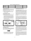
c. Mark the instrument clearl
y
with a ta
g
or label indicatin
g
the correct line volta
g
e to be used.
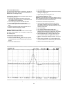
Fi
g
ure A-2. Line Volta
g
e Selector (set for 115 Vac)
PERFORMANCE TESTS
The followin
g
para
g
raphs provide test procedures for verif
y
-
in
g
the power suppl
y
's compliance with the specifications of
Table 1. Proceed to the troubleshootin
g
procedures if
y
ou
observe an
y
out of specification performance.
Before appl
y
in
g
power to the suppl
y
, make certain
that its line volta
g
e selector switch (S2) is set for the
line volta
g
e to be used. (See CAUTION notice in
operatin
g
section for additional information on S2.)
General Measurement Techniques
Connectin
g
Measurin
g
Devices. To achieve valid results
when measurin
g
load re
g
ulation, ripple and noise, and tran-
sient response time of the suppl
y
, measurin
g
devices must be
connected as close to the output terminals as possible. A
measurement made across the load includes the impedance
of the leads to the load. The impedance of the load leads can
easil
y
be several orders of the ma
g
nitude
g
reater than the
suppl
y
impedance and thus invalidate the measurement. To
avoid mutual couplin
g
effects, each measurin
g
device must
be connected directl
y
to the output terminals b
y
separate
pairs of leads.
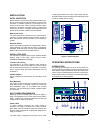
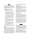
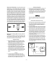
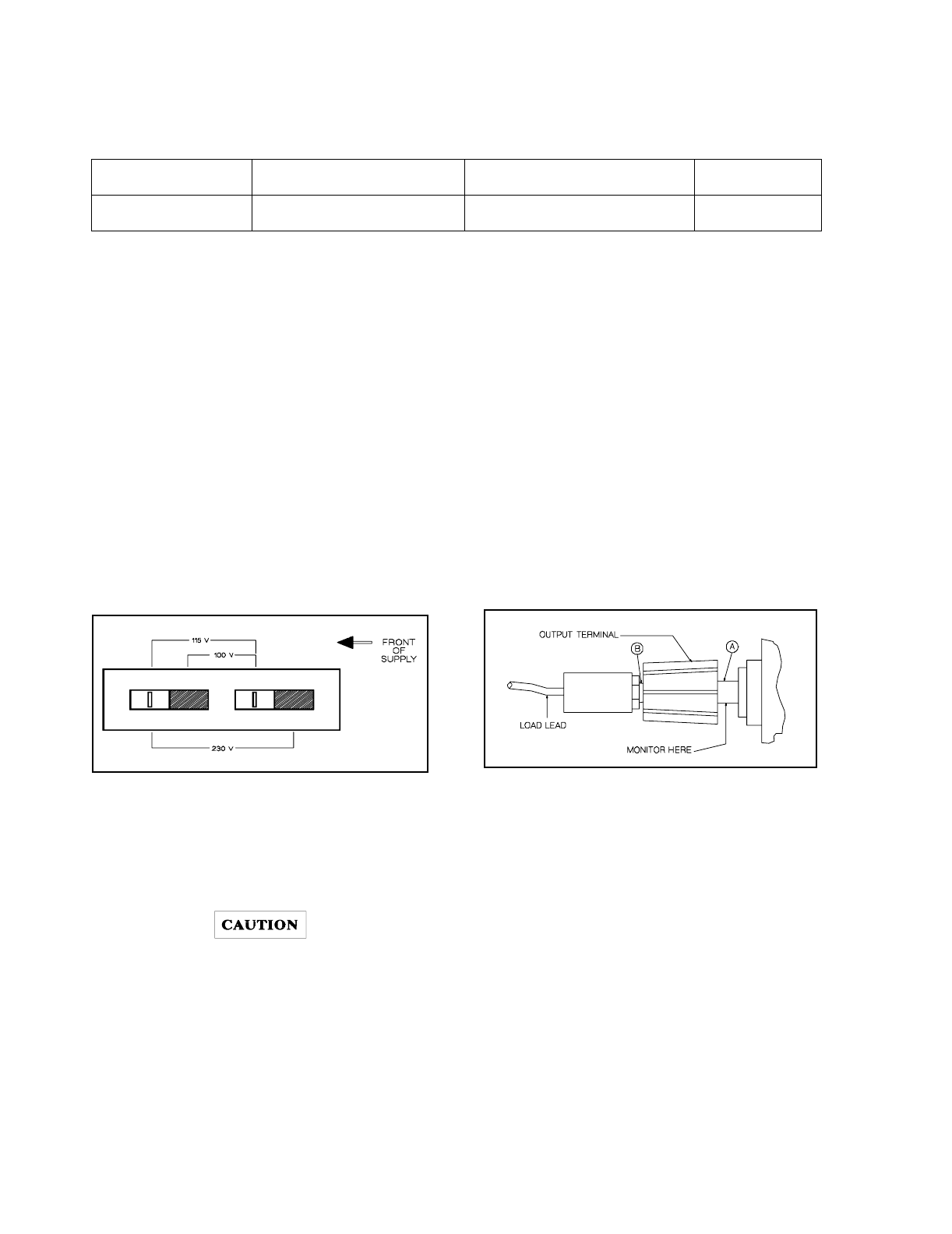
When performance measurements are made at the front ter-
minals (Fi
g
ure A-3) the load should be plu
gg
ed into the front
of the terminals at (B) while the monitorin
g
device is con-
nected to a small lead or bus wire inserted throu
g
h the hole in
the neck of the bindin
g
post at (A). Connectin
g
the measurin
g
device at (B) would result in a measurement that includes the
resistance of the leads between the output terminals and the
point of connection.
Fi
g
ure A-3. Front Panel Terminal Connections
Selectin
g
Load Resistors. Power suppl
y
specifications are
checked with a full load resistance connected across the sup-
pl
y
output. The resistance and watta
g
e of the load resistor,
therefore, must permit operation of the suppl
y
at its rated out-
put volta
g
e and current. For example, a suppl
y
rated at 20
volts and 0.5 amperes would require a load resistance of 40 Ω
at the rated output volta
g
e. The watta
g
e ratin
g
of this resistor
would have to be at least 20 watts.
Electronic Load. Some of the performance test procedures
use an electronic load to test the suppl
y
quickl
y
and accu-
ratel
y
. An electronic load is considerabl
y
easier to use than a
load resistor. It eliminates the need for connectin
g
resistors or
rheostats in parallel to handle the power, it is much more sta-
ble than a carbon-pile load. It is easier to switch between load
conditions as required for the load re
g
ulation and load tran-
sient response tests.
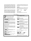
Current Samplin
g
Resistor (Shunt)
100 mΩ 0.1% 15 W Measure output current
Variable Volta
g
e
Auto Transformer
Ran
g
e : 85-130 and 200-260
Volts
Var
y
ac input.
Table A-1. Test Equipment Required (Cont’d)


Find Your Products By Category
- Household Appliance
- Power Tools
- Computer Equipment
- Automotive
- TV and Video
- Outdoor Cooking
- Marine Equipment
- Kitchen Appliance
- Fitness & Sports
- Lawn and Garden
- Baby
- Laundry Appliance
- Personal Care
- Home Audio
- Photography
- Video Game
- Portable Media
- Musical Instruments & Equipment
- Communications
- Car Audio and Video
Please Login
