
0
Owner's of the Agilent Technologies Power Supply Agilent Technologies Power Supply gave it a score of 0 out of 5. Here's how the scores stacked up:
1-4
GENERAL INFORMATION
INTRODUCTION
This section contains general information concerning the
E3630A triple output power supply. Included are safety con-
siderations, safety and EMC requirements, instrument and
manual identification, option and accessory information,
instrument description, and specifications.
SAFETY CONSIDERATIONS
This product is a Safety Class I instrument, which means that
it is provided with a protective earth ground terminal. This ter-
minal must be connected to an ac source that has a 3-wire
ground receptacle. Review the instrument rear panel and this
manual for safety markings and instructions before operating
the instrument. Refer to the Safety Summary page at the
beginning of this manual for a summary of general safety
information. Specific safety information is located at the
appropriate places in this manual.
SAFETY AND EMC REQUIREMENTS
This power supply is designed to comply with the following
safety and EMC(Electromagnetic Compatibility) require-
ments:
n IEC 1010-1(1990)/EN 61010 (1993): Safety Require-
ments for Electrical Equipment for Measurement, Control,
and Laboratory Use
n CSA C22.2 No.231: Safety Requirements for Electrical
and Electronic Measuring and Test Equipment
n UL 1244: Electrical and Electronic Measuring and Testing
Equipment
n EMC Directive 89/336/EEC: Council Directive entitled
Approximation of the Laws of the Member States relating
to Electromagnetic Compatibility
n EN 55011(1991) Group 1, Class B/CISPR 11 (1990): Lim-
its and Methods of Radio Interference Characteristics of
Industrial, Scientific, and Medical(ISM) Radio - Fre-
quency Equipment
n EN 50082-1(1992) /
IEC 801-2(1991): Electrostatic Discharge Require-
ments
IEC 801-3(1984): Radiated Electromagnetic Field
Requirements
IEC 801-4(1988): Electrical Fast Transient/Burst
Requirements
INSTRUMENT AND MANUAL IDENTIFICATION
A serial number identifies your power supply. The serial num-
ber encodes the country of manufacture, the week of the lat-
est significant design change, and a unique sequential
number. The letter "KR" designates Korea as the country of
manufacture, the first one digit indicates the year (3=1993,
4=1994, and so forth), and the second two digits indicate the
week. The remaining digits of the serial number are a unique,
five-digit number assigned sequentially.
If the serial number on your supply does not agree with those
on the title page of the manual, a yellow Change Sheet is
supplied with the manual to explain the difference
between your instrument and the instrument described by this
manual. The Change Sheet may also contain information for
correcting errors in the manual.
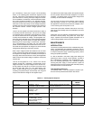
OPTIONS
Options OE3 and OE9 determine which line voltage is
selected at the factory. The standard unit is configured for 115
Vac ± 10%, 47-63 Hz input.
Option No. Description
OE3: 230 Vac ± 10%, 47-63 Hz Input
OE9: 100 Vac ± 10%, 47-63 Hz Input
910: One additional operating and service manual
shipped with the power supply
ACCESSORY
The accessory listed below may be ordered from your local
Agilent Technologies Sales Office either with the power sup-
ply or separately. (Refer to the list at the rear of the manual for
address.)
Agilent Part No.Description
5063-9767 Rack Kit for mounting one or two 3 1/2" high
supplies in a standard 19" rack
The rack mount kit is needed for rack mounting of the
E3630A power supply.
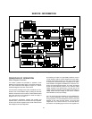
DESCRIPTION
This constant-voltage/current-limiting triple output power sup-
ply combines two 0 to ±20V tracking outputs rated at 0.5
amps with an additional single output that is rated at 0 to 6
volts and 2.5 amps. The +20V and -20V tracking outputs can
also be used in series as a single 0 to 40V 0.5-amp output.
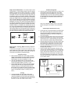
Connections to the supply's output and to chassis ground are
made to binding posts on the front panel. The supply's three
outputs share a common output terminal, which is isolated
from chassis ground so that any one output terminal can be
grounded.
All outputs are protected against overload and short-circuit
damage. The ±20V outputs are protected by circuits that limit
the output current to 110% of its nominal maximum. The over-
load protection circuit for the +6V output has a current fold-
back characteristic that reduces the output current as an
overload increases until only 1 amp flows through a short cir-
cuit. The 6V output current limit depends on the output termi-
nal voltage and varies linearly between 2.75 amps at 6 volts
and 1 amp at zero volts.
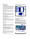
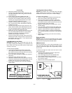
All controls, digital meter, and output terminals are located on the
front panel. One voltage control sets the 0 to 6V and another
sets the voltages of the 0 to +20V and 0 to -20V outputs simul-
taneously. These dual tracking outputs are made more versatile
by providing a tracking ratio control in addition to the usual volt-
age control. With the tracking ratio control turned fully clockwise
to its "fixed" position, the dual outputs have a fixed 1:1 tracking
ratio. As the ±20V voltage control is adjusted, the voltage of the
negative supply tracks the positive output within ±1%. Turning
the tracking ratio control away from its fully clockwise position
switches the dual tracking outputs into a variable tracking ratio


Find Your Products By Category
- Household Appliance
- Power Tools
- Computer Equipment
- Automotive
- TV and Video
- Outdoor Cooking
- Marine Equipment
- Kitchen Appliance
- Fitness & Sports
- Lawn and Garden
- Baby
- Laundry Appliance
- Personal Care
- Home Audio
- Photography
- Video Game
- Portable Media
- Musical Instruments & Equipment
- Communications
- Car Audio and Video
Please Login
