

0
Owner's of the Agilent Technologies Power Supply Agilent Technologies Power Supply gave it a score of 0 out of 5. Here's how the scores stacked up:

1-6
INSTALLATION
INITIAL INSPECTION
Before shipment, this instrument was inspected and found to
be free of mechanical and electrical defects. As soon as the
instrument is unpacked, inspect for any damage that may
have occurred in transit. Save all packing materials until the
inspection is completed. If damage is found, a claim should
be filed with the carrier. The Agilent Technologies Sales and
Service office should be notified as soon as possible.
Mechanical Check
This check should confirm that there are no broken knobs or
connectors, that the cabinet and panel surfaces are free of
dents and scratches, and that the meter is not scratched or
cracked.
Electrical Check
Perform the TURN-ON CHECKOUT PROCEDURE in the fol-
lowing paragraph to confirm that the supply is operational.
Alternately, check the supply more fully using the PERFOR-
MANCE TEST in the service information section.
INSTALLATION DATA
The instrument is shipped ready for bench operation. Before
applying power to the supply, please read the INPUT
POWER REQUIREMENTS paragraph.
Location and Cooling
This instrument is air cooled. Sufficient space should be
allowed so that a free flow of cooling air can reach the sides
and rear of the instrument when it is in operation. It should be
used in an area where the ambient temperature does not
exceed 40
o
C.
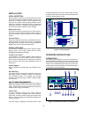
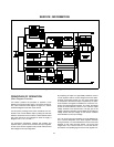
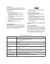
Outline Diagram
Figure 1 illustrates the outline shape and dimensions of the
supply.
Rack Mounting
This supply may be rack mounted in a standard 19-inch rack
panel either by itself or alongside a similar unit. Please see
the ACCESSORY, page 1-4, for available rack mounting
accessory. The rack-mounting kit includes complete installa-
tion instructions.
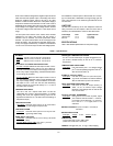
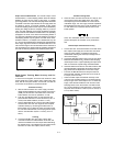
INPUT POWER REQUIREMENTS
Depending on the line voltage option ordered, the supply is
ready to be operated from one of the power sources listed in
Table 1. A label on the rear heat sink shows the nominal input
voltage set for the supply at the factory.
Power Cable
To protect operating personnel, the supply should be
grounded. This supply is equipped with a three conductor
power cable. The third conductor is the ground conductor and
when the cable is plugged into an appropriate receptacle, the
supply is grounded.
The power supply is equipped at the factory with a power
cord plug appropriate for the user's location. Notify the near-
est Agilent Sales and Service Office if the appropriate power
cord is not included with the supply.
Figure 1. Outline Diagram
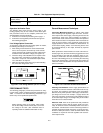
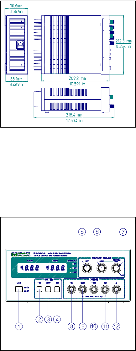
OPERATING INSTRUCTIONS
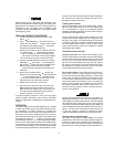
INTRODUCTION
The following steps describe the use of the front panel con-
trols and indicators illustrated in Figure 2 and serve as a brief
check that the supply is operational. Follow this checkout pro-
cedure or the more detailed performance test of service infor-
mation section when the instrument is received and before it
is connected to any load equipment.
Figure 2. Front-Panel Controls and Indicators


Find Your Products By Category
- Household Appliance
- Power Tools
- Computer Equipment
- Automotive
- TV and Video
- Outdoor Cooking
- Marine Equipment
- Kitchen Appliance
- Fitness & Sports
- Lawn and Garden
- Baby
- Laundry Appliance
- Personal Care
- Home Audio
- Photography
- Video Game
- Portable Media
- Musical Instruments & Equipment
- Communications
- Car Audio and Video
Please Login
