
0
Owner's of the Agilent Technologies Power Supply Agilent Technologies Power Supply gave it a score of 0 out of 5. Here's how the scores stacked up:

A-2
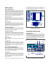
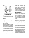
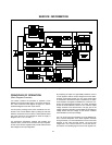
put is enclosed by a heavy line in Figure 3 of the operating
section. If the operating point reaches the diagonal current
limit line, a decrease in load resistance moves the operating
point down the line, reducing the output voltage and current.
Current foldback is controlled by a second operational ampli-
fier (current comparison amplifier) in the regulator that moni-
tors the dc output current. This current comparison amplifier
takes control of the output away from the voltage comparison
amplifier when the current reaches the design limit. Removing
the overload restores constant voltage operation auto-
matically.
The 0 to +20-volt regulator has a fixed current limit at 105% of
its 0.5 amp maximum rated output. The input ac line voltage
is first applied to the preregulator which operates in conjunc-
tion with the SCR control circuit (preregulator control circuit)
to rectify the tap switched AC voltage. This preregulator mini-
mizes the power dissipated in the series regulating elements
by controlling the dc level across the input filter capacitor,
depending on the output voltage. To achieve this, tap switch-
ing is accomplished by two SCRs and one bridge diode
(CR28, CR32 and CR26) and the SCR control circuit. This cir-
cuit allows the input capacitor to charge to one of two discrete
voltage levels depending on the output required.
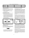
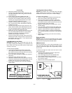
When output voltage exceeds the reference level, the SCR
control circuit fires two SCRs that cause the input capacitor to
be charged to the voltage which is necessary for full output of
the supply. When the two SCRs are not fired, the bridge diode
CR26 conducts and half the voltage is applied to series pass
transistor Q9.
The 0 to -20-volt regulator is, in turn, similar to the +20-volt
regulator except that it resembles a complementary mirror
image of the latter. The output voltages of the +20-volt and -
20-volt supplies are both set by the same front panel control
and track each other within 1% in the fixed tracking ratio
mode. Precise tracking of the two outputs is achieved by
controlling the positive output conventionally and using that
output as the reference voltage for the negative output.
The reference and bias supply powers the operation amplifi-
ers and provides reference and bias voltages for the output
regulators. The display power circuit provides voltage which
is used by the A/D converter and display.
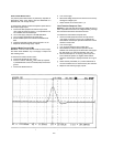
The turn-on/turn-off control circuit prevents output transients
when the supply is turned on or off. It does this by delaying
the application of certain bias and reference voltages at turn-
on and removing them shortly after turn-off.
Three meter push-button switches select which of the sup-
plies has its output voltage and current indicated on the front
panel meters.
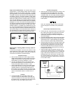
Diode CR2, CR3, and CR4 are connected across the output
terminals in reverse polarity. They protect the output elec-
trolytic capacitor and the series regulator transistors from a
reverse voltage applied across the output terminals.
MA INTENANCE
INTRODUCTION
This section provides performance test, troubleshooting infor-
mation, and adjustment and calibration procedures. The fol-
lowing operation verification tests comprise a short procedure
to verify that the power supply is performing properly, without
testing all specified parameters.
If a fault is detected in the power supply while making the
performance check or during normal operation, proceed to
the troubleshooting procedures. After troubleshooting, per-
form any necessary adjustments and calibrations. Before
returning the power supply to normal operation, repeat the
performance check to ensure that the fault has been properly
corrected and that no other faults exist.
Test Equipment Required
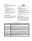
The following Table A-1 lists the equipment required to per-
form the various procedures described in this section.
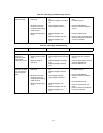
Table A-1. Test Equipment Required
TYPE REQUIRED CHARACTERISTICS USE RECOMMENDED
MODEL
Oscilloscope Sensitivity : 100 mV
Bandwidth : 20 MHz/100 MHz
Display transient response and ripple
and noise waveforms.
Agilent 54600A
RMS Voltmeter True rms, 20 MHz bandwidth
Sensitivity : 1 mV
Accuracy : 5%
Measure rms ripple and noise
voltage.
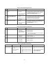
Multimeter Resolution : 100 nV
Accuracy : 0.0035%
Measure dc voltages. Agilent 34401A
Electronic Load Voltage Range : 240 Vdc
Current Range : 10 Adc
Open and short switches
Transient on/off
Measure load and line regulation. Agilent 6063A
Resistive Loads (R
L
) 40 W 20 W, 2.4 W 20 W Measure ripple and noise.


Find Your Products By Category
- Household Appliance
- Power Tools
- Computer Equipment
- Automotive
- TV and Video
- Outdoor Cooking
- Marine Equipment
- Kitchen Appliance
- Fitness & Sports
- Lawn and Garden
- Baby
- Laundry Appliance
- Personal Care
- Home Audio
- Photography
- Video Game
- Portable Media
- Musical Instruments & Equipment
- Communications
- Car Audio and Video
Please Login
