
0
Owner's of the Agilent Technologies Power Supply Agilent Technologies Power Supply gave it a score of 0 out of 5. Here's how the scores stacked up:
A-4
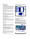
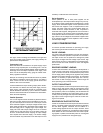
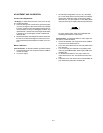
Output Current Measurement. For accurate output current
measurements, a current sampling resistor should be inserted
between the load and the output of the supply. To simplify
grounding problems, one end of this sampling resistor should be
connected to the same output terminal of the supply which will
be shorted to ground. An accurate voltmeter is then placed
across the sampling resistor and the output current calculated by
dividing the voltage across the sampling resistor by its ohmic
value. The total resistance of the series combination should be
equal to the full load resistance as determined in the preceding
paragraphs. Of course, if the value of the sampling resistor is
very low when compared to the full load resistance, the value of
the sampling resistor may be ignored. The meter shunt recom-
mended in Table A-1, for example, has a resistance of only 100
mW and can be neglected when calculating the load resistance
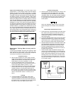
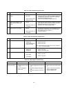
of the supply. Figure A-4 shows a four terminal meter shunt. The
load current through a shunt must be fed from the extremes of
the wire leading to the resistor while the sampling connections
are made as close as possible to the resistance portion itself.
Figure A-4. Current Sampling Resistor Connections
Rated Output, Tracking, Meter Accuracy, and Cur-
rent Limit
To check that all supplies will furnish their maximum rated
output voltage and current, that the ±20V outputs track each
other, that the front panel meters are accurate, and that the
current limit circuits function, proceed as follows:
Voltmeter Accuracy
a. With no loads connected: turn on the supply, connect a
digital voltmeter between the +20V terminal and common
(COM), and set the ±20V VOLTAGE control so that the
DVM indication is as near as possible to 17 volts.
b. Push the +20V METER switch on and check the front
panel voltmeter indication. It should be within ±(0.5% +2
counts) of the DVM indication (16.90V to 17.10V).
c. Set the TRACKING RATIO control to the FIXED position,
and check the +20V and -20V ranges of the front panel
voltmeter similarly by connecting the DVM to each of
these outputs in turn, setting the ±20V VOLTAGE control
for a 20 volts DVM indication, and verifying that the panel
meter is accurate within ±(0.5%+ 2 counts) (19.7V to
20.3V).
Tracking
d. Connect the DVM to the +20V output, set the ±20V
VOLTAGE control for a DVM indication of 20 volts, and
reconnect the DVM to the -20V output without disturbing
the voltage control. The voltage at the -20V output should
be within 1% of the +20V output (19.8V to 20.2V).
Variable Tracking Ratio
e. Leave the ±20V VOLTAGE control set as in step (d), and
use a DVM to monitor the voltage of the -20V supply
while adjusting the TRACKING RATIO control over its
VARIABLE range. The -20V supply should be capable of
being adjusted from less than 0.5 volts to between 19 to
21 volts. Return the TRACKING RATIO control to the
FIXED position.
Leave the TRACKING RATIO control in the FIXED
position throughout the reminder of the performance
test.
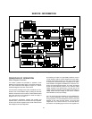
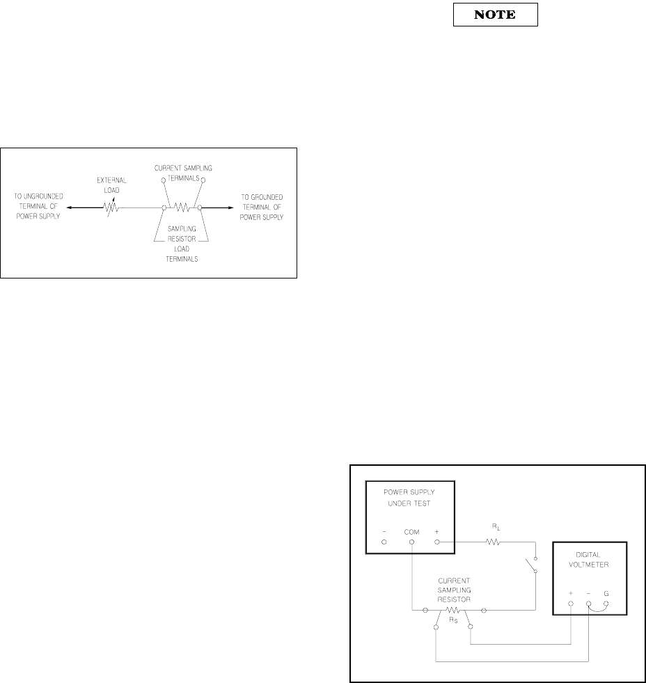
Rated Output and Ammeter Accuracy
f. Connect two 40W 20 W load resistors across both of the
20V outputs of the supply and set the ±20V VOLTAGE
control for ±20V outputs. (All supplies must be fully
loaded while checking the rated output voltage and cur-
rent of each supply.)
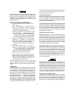
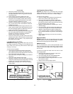
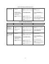
g. Connect the test setup shown Figure A-5 to the +6V output.
Make the total resistance of R
L
and the current sampling
resistor equal to 2.4W to permit operating the output at full
load. R
L
should have a power rating of at least 20 watts.
h. Close the switch and set the +6V VOLTAGE control so that
the DVM indicates a voltage drop across the current sam-
pling resistor that corresponds to a current of 2.5 amps.
i. Push the +6V METER switch and verify that the front
panel ammeter indication is within ±(0.5%+2 counts) of
2.5 amps (2.47A to 2.53A).
j. Check the rated output and ammeter accuracy of the
+20V and -20V supplies similarly by connecting the test
setup of Figure A-5 to each output in turn. For each 20V
supply: make the total resistance of R
L
and the current
sampling resistor 40 W, set the ±20V VOLTAGE control
for a current indication on the DVM of 0.5 A, check that
the panel meter indication is within ±(0.5%+2 counts) of
0.5 A (0.48A to 0.52A).
Figure A-5. Output Current, Test Set UP


Find Your Products By Category
- Household Appliance
- Power Tools
- Computer Equipment
- Automotive
- TV and Video
- Outdoor Cooking
- Marine Equipment
- Kitchen Appliance
- Fitness & Sports
- Lawn and Garden
- Baby
- Laundry Appliance
- Personal Care
- Home Audio
- Photography
- Video Game
- Portable Media
- Musical Instruments & Equipment
- Communications
- Car Audio and Video
Please Login
