
0
Owner's of the Agilent Technologies Power Supply Agilent Technologies Power Supply gave it a score of 0 out of 5. Here's how the scores stacked up:

A-6
Peak-to-Peak Measurement
The peak-to-peak measurement is particularly important for
applications where noise spikes could be detrimental to a
sensitive load, such as logic circuitry.
To measure the ripple and noise of the peak-to-peak value on
each output supply output:
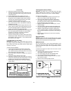
a. Connect the test equipment across the output of the
+20V supply as shown in Figure A-7, but replace the true
rms voltmeter with the oscilloscope.
b. Turn on the supply and push +20V METER switch.
c. Turn up output voltage to the full rated value.
d. Set the oscilloscope to AC mode and bandwidth to 20
MHz.
e. Check that the peak-to-peak noise is less than 1.5 mV.
f. Repeat for the remaining supply outputs.
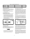
Common Mode Current (CMI)
Definition : Common mode current is that ac current compo-
nent which exists between any or all supply or output lines
and chassis ground.
To measure the common mode current:
a. Connect the full load for +6V output.
b. Connect a 100 kW resistor(R
S
) and a 2200 pF capacitor
in parallel between common terminal(COM) and chassis
ground.
c. Connect the DVM across R
S
.
d. Turn on the supply.
e. Record the voltage across R
S
and convert it to current by
dividing this voltage by R
S
.
f. Check that the current is less than 1 mA.
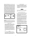
Load Transient Response Time
Definition : This is the time for the output voltage to return to
within a specified band around its voltage following a change
from full load to half load or half load to full load.
To measure the load transient response time:
a. Connect the test equipment across the output of the
+20V supply as shown in Figure A-6, but replace the
DVM with the oscilloscope. Operate the electronic load in
constant current mode.
b. Turn on the supply.
c. Turn up output voltage to the full rated value.
d. Set the electronic load to transient operation mode
between one half of supply's full rated value and supply's
full rated value at a 1 KHz rate with 50% duty cycle.
e. Set the oscilloscope for ac coupling, internal sync and
lock on either the positive or negative load transient.
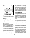
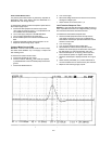
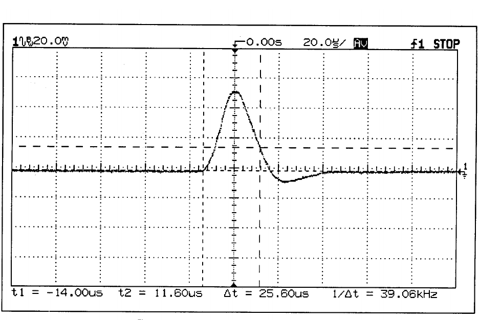
f. Adjust the oscilloscope to display transients as in Figure
A-8.
g. Check that the pulse width (t
2
-t
1
) of the transients at 15
mV from the base line is no more than 50 msec as shown.
h. Repeat for the remaining supply outputs.
Figure A-8. Load Transient Response Time Waveform


Find Your Products By Category
- Household Appliance
- Power Tools
- Computer Equipment
- Automotive
- TV and Video
- Outdoor Cooking
- Marine Equipment
- Kitchen Appliance
- Fitness & Sports
- Lawn and Garden
- Baby
- Laundry Appliance
- Personal Care
- Home Audio
- Photography
- Video Game
- Portable Media
- Musical Instruments & Equipment
- Communications
- Car Audio and Video
Please Login
