
0
Owner's of the Agilent Technologies Power Supply Agilent Technologies Power Supply gave it a score of 0 out of 5. Here's how the scores stacked up:
A-5
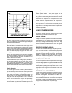
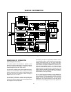
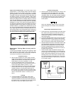
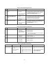
Current Limit
k. Disconnect all loads from the suppl
y
.
l. Connect the test setup shown in Fi
g
ure A-5 to the +20-
volt output. Substitute a short for R
L
and leave the load
circuit switch open.
m. Set the volta
g
e of the ±20V supplies to 20 volts.
n. Close the load switch and determine the current flow
throu
g
h the current samplin
g
resistor (meter shunt) b
y
measurin
g
its volta
g
e drop with the DVM. The current
should be 0.55A±5% (0.5225A to 0.5775A).
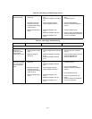
o. Check the current limit of the -20V suppl
y
in the same
wa
y
. Its short-circuit current should also be 0.55A±5%
(0.5225A to 0.5775A).
p. Connect the test setup shown in Fi
g
ure A-5 to the +6V
output. Close the switch, set the total resistance of R
L
and
the current samplin
g
resistor to an initial value of 2.4 Ω or
g
reater, and set the output volta
g
e to 6 volts.
q. Reduce the value of R
L
g
raduall
y
while observin
g
the out-
put current indicated b
y
the DVM. The current should
increase to a maximum of 2.75A±5% (2.6125A to
2.8875A) before it be
g
ins to decrease.
r. Connect a short across R
L
and then recheck the current
indicated b
y
the DVM. The short-circuit current of this out-
put should be 1A±15% (0.85A to 1.15A). Disconnect the
test setup from the suppl
y
.
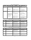
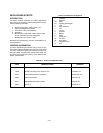
Load Re
g
ulation (Load Effect)
Definition: The chan
g
e, E
OUT
, in the static value of dc out-
put volta
g
e resultin
g
from a chan
g
e in load resistance from
open circuit to the value that
y
ields maximum rated output
current (or vice versa).
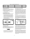
To check the load re
g
ulation:
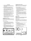
a. Connect the test equipment across the output of the
+20V suppl
y
as shown in Fi
g
ure A-6. Operate the elec-
tronic load in constant current mode and set its current to
the full rated value of the +20V suppl
y
.
b. Turn on the suppl
y
and adjust its volta
g
e to its maximum
rated value.
c. Record the volta
g
e indicated on the DVM.
d. Operate the electronic load in open (input off) mode and
recheck the DVM indication after readin
g
settles. It should
be within 0.01% plus 2mV of the readin
g
in step (c).
e. Repeat steps (a) throu
g
h (d) for each of the remainin
g
suppl
y
outputs.
Fi
g
ure A-6. Basic Test Setup
Line Re
g
ulation (Source Effect)
Definition: The chan
g
e, E
OUT
, in the static value of dc output
volta
g
e resultin
g
from a chan
g
e in ac input volta
g
e from a
minimum to a maximum value (±10% of nominal volta
g
e).
To check the line re
g
ulation:
a. Connect a variable autotransformer between the input
power source and the power suppl
y
line plu
g
.
b. Connect the test equipment across the output of the
+20V suppl
y
as shown in Fi
g
ure A-6. Operate the elec-
tronic load in constant current mode and set its current to
the full rated value of the +20V suppl
y
.
c. Adjust the autotransformer for a low line input (-10% of
nominal volta
g
e).
d. Turn on the power, adjust the output of the suppl
y
to its
maximum rated volta
g
e, and record the DVM indication.
e. Adjust the autotransformer for hi
g
h line volta
g
e input
(+10% of nominal volta
g
e) and recheck the DVM indica-
tion. It should be within 0.01% plus 2mV of the readin
g
in
step (d).
f. Repeat steps (b) throu
g
h (e) for each of the remainin
g
suppl
y
outputs.
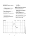
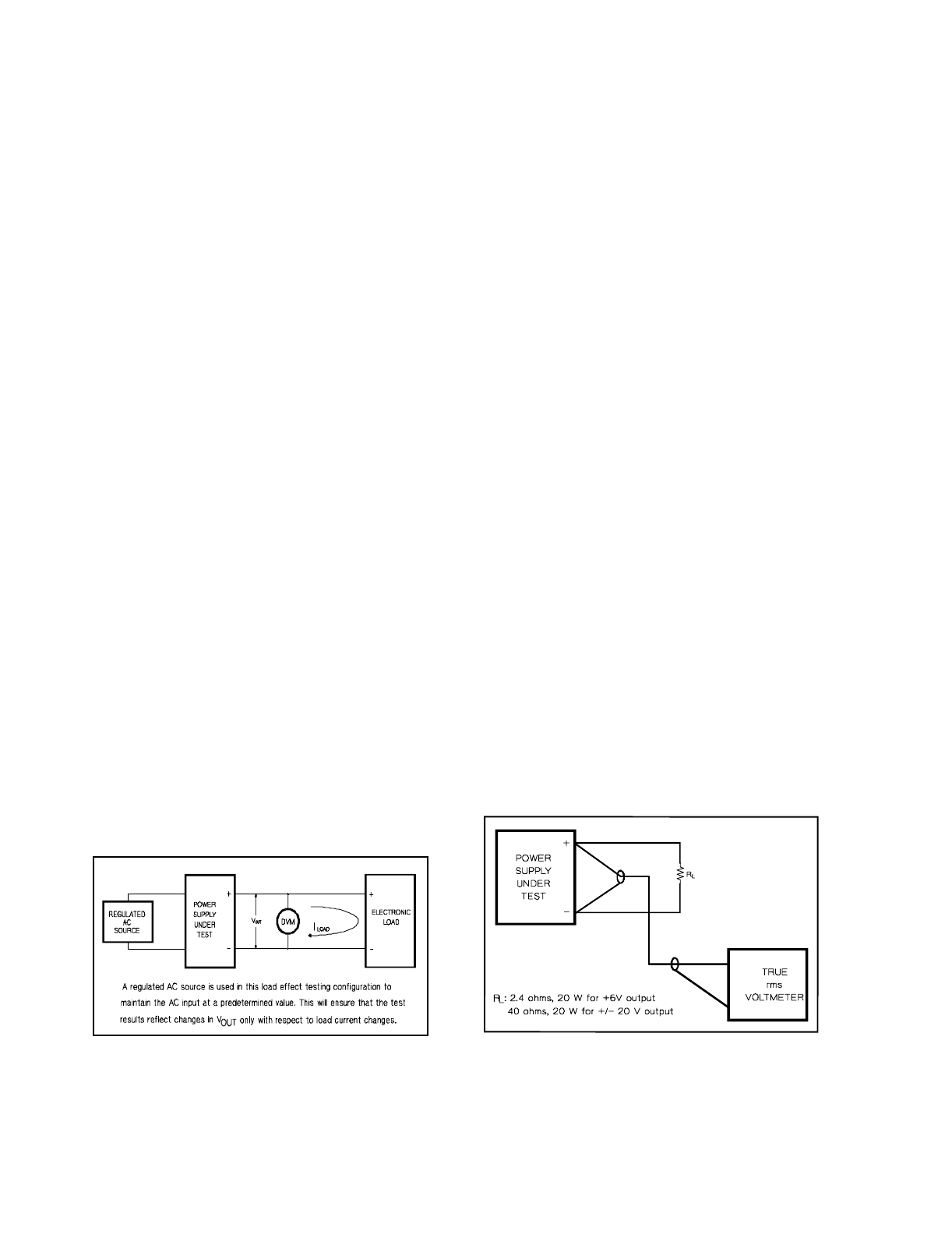
Ripple and Noise
Definition: Ripple and noise are measured in the rms or peak-
to-peak value over a 20 Hz to 20 MHz bandwidth. Fluctuations
below the lower frequenc
y
limit are treated as drift.
RMS Measurement
The rms measurement is not an ideal representation of the
noise, since fairl
y
hi
g
h output noise spikes of short duration
could be present in the ripple and not appreciabl
y
increase
the rms value.
To measure the ripple and noise of the rms value on each
output suppl
y
output:
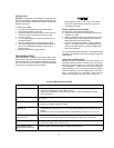
a. Connect the test equipment across the output of the
+20V suppl
y
as shown in Fi
g
ure A-7.
b. Turn on the suppl
y
and push +20V METER switch.
c. Turn up output volta
g
e to the full rated value.
d. Check that the rms noise volta
g
e at the true rms voltme-
ter is less than 0.35mV.
e. Repeat for the remainin
g
suppl
y
outputs.
Fi
g
ure A-7. Ripple and Noise rms Measurement Test
Setup


Find Your Products By Category
- Household Appliance
- Power Tools
- Computer Equipment
- Automotive
- TV and Video
- Outdoor Cooking
- Marine Equipment
- Kitchen Appliance
- Fitness & Sports
- Lawn and Garden
- Baby
- Laundry Appliance
- Personal Care
- Home Audio
- Photography
- Video Game
- Portable Media
- Musical Instruments & Equipment
- Communications
- Car Audio and Video
Please Login
