
0
Owner's of the Agilent Technologies Welding System Agilent Technologies Welding System gave it a score of 0 out of 5. Here's how the scores stacked up:

Chapter 3 Calibration Procedures
Constant Current (CC) Verifications
58
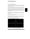
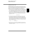
Normal Mode Current Noise (CC Ripple and Noise)
The normal mode current noise is specified as the rms output current in a
frequency range 20 Hz to 20 MHz with the power supply in constant current
operation.
1
Turn off the power supply and connect the output to be tested as shown in Figure
3-1 with a load resistor (1.2
9
for +6V supply and 25
9
for ±25V supplies) across
output terminals to be tested. Connect a rms voltmeter across the load resistor.
Use only a resistive load for this test.
2
Turn on the power supply and select the output to be tested using the meter
selection key on the front panel. Enable the outputs and set the display to the
limit mode. When the display is in the limit mode, program the current to full-
scale value and the voltage to the maximum programmable value.
3
The output current should be at the full-scale rating with the CC annunciator
on. If not lit, adjust the load so that the output voltage drops slightly until the
CC annunciator lights.
4
Divide the reading on the rms voltmeter by the load resistance to obtain rms
current. The readings should be within the limit specified below for each
output tested.
5
Repeat steps (1) through (4) for the remaining outputs.
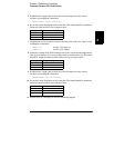
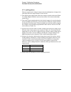
Output Specification
+6V 2 mA
+25V 0.5 mA
-25V 0.5 mA


Find Your Products By Category
- Household Appliance
- Power Tools
- Computer Equipment
- Automotive
- TV and Video
- Outdoor Cooking
- Marine Equipment
- Kitchen Appliance
- Fitness & Sports
- Lawn and Garden
- Baby
- Laundry Appliance
- Personal Care
- Home Audio
- Photography
- Video Game
- Portable Media
- Musical Instruments & Equipment
- Communications
- Car Audio and Video
Please Login
