
0
Owner's of the Agilent Technologies Welding System Agilent Technologies Welding System gave it a score of 0 out of 5. Here's how the scores stacked up:


Chapter 3 Calibration Procedures
Constant Voltage (CV) Verifications
52
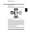
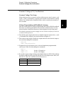
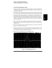
Common Mode Current Noise
The common mode current is that ac current component which exists between
any or all outputs or output lines and chassis ground. Common mode noise can
be a problem for very sensitive circuitry that is referenced to earth ground.
When a circuit is referenced to earth ground, a low level line-related ac current
will flow from the output terminals to earth ground. Any impedance to earth
ground will create a voltage drop equal to the output current flow multiplied
by the impedance.
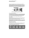
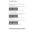
1
Turn off the power supply and connect a 100 k
W
resistor (R
S
) and a 2200 pF
capacitor in parallel between the (-) terminal and chassis ground for +6V output
or between the (COM) terminal and chassis ground for ±25V outputs.
2
Connect a digital voltmeter across R
S
.
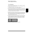
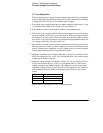
3
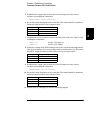
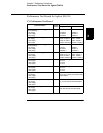
Turn on the power supply and select the output to be tested using the meter
and adjust selection key on the front panel. Enable the outputs and set the
display to the limit mode. When the display is in the limit mode, program the
current of the selected output to the maximum programmable value and the
voltage to the full-scale value (see Table 3-2).
4
Record the voltage across R
S
and convert it to current by dividing by the
resistance (DVM reading/100 k
W
). Note that the current is less than 1.5
m
A for
each of the three outputs.
5
Repeat steps (1) through (4) for the remaining outputs.


Find Your Products By Category
- Household Appliance
- Power Tools
- Computer Equipment
- Automotive
- TV and Video
- Outdoor Cooking
- Marine Equipment
- Kitchen Appliance
- Fitness & Sports
- Lawn and Garden
- Baby
- Laundry Appliance
- Personal Care
- Home Audio
- Photography
- Video Game
- Portable Media
- Musical Instruments & Equipment
- Communications
- Car Audio and Video
Please Login
