

0
Owner's of the Agilent Technologies Welding System Agilent Technologies Welding System gave it a score of 0 out of 5. Here's how the scores stacked up:


Chapter 3 Calibration Procedures
Constant Voltage (CV) Verifications
47
3
Constant Voltage (CV) Verifications
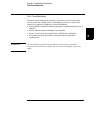
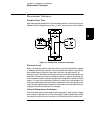
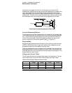
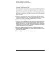
Constant Voltage Test Setup
If more than one meter or a meter and an oscilloscope are used, connect each
to the (+) and (-) terminals by a separate pair of leads to avoid mutual coupling
effects. Use coaxial cable or shielded 2-wire cable to avoid noise pick-up on
the test leads.
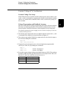
Voltage Programming and Readback Accuracy
This test verifies that the voltage programming and GPIB or RS-232 readback
functions are within specifications. Note that the readback values over the
remote interface should be identical to those displayed on the front panel.
You should program the power supply over the remote interface for this test
to avoid round off errors.
1
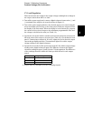
Turn off the power supply and connect a digital voltmeter between the (+) and
(-) terminals of the output to be tested as shown in Figure 3-1.
2
Turn on the power supply. Enable the outputs and select the desired output to
be tested by sending the commands:
OUTP ON
INST {P6V|P25V|N25V}
3
Program the selected output to zero volts and maximum programmable
current (see Table 3-2) by sending the commands:
VOLT 0
CURR 5.15
for the +6V supply or
CURR 1.03
for the ±25V supply
4
Record the output voltage reading on the digital voltmeter (DVM). The readings
should be within the limits specified below for each output tested. Also, note
that the CV, Adrs, Lmt, and Rmt annunciators are on.
Output Programming Accuracy
+6V 0 ± 5 mV
+25V 0
± 20 mV
-25V 0
± 20 mV


Find Your Products By Category
- Household Appliance
- Power Tools
- Computer Equipment
- Automotive
- TV and Video
- Outdoor Cooking
- Marine Equipment
- Kitchen Appliance
- Fitness & Sports
- Lawn and Garden
- Baby
- Laundry Appliance
- Personal Care
- Home Audio
- Photography
- Video Game
- Portable Media
- Musical Instruments & Equipment
- Communications
- Car Audio and Video
Please Login
