
0
Owner's of the Agilent Technologies Welding System Agilent Technologies Welding System gave it a score of 0 out of 5. Here's how the scores stacked up:


Chapter 3 Calibration Procedures
Constant Voltage (CV) Verifications
53
3
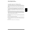
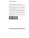
Load Transient Response Time
This test measures the time for the output voltage to recover to within 15 mV
of nominal output voltage following a load change from full load to half load,
or half load to full load.
1
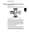
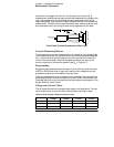
Turn off the power supply and connect the output to be tested as shown in Figure
3-1 with an oscilloscope. Operate the electronic load in constant current mode.
2
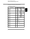
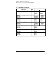
Turn on the power supply and select the output to be tested using the meter
and adjust selection key on the front panel. Enable the outputs and set the
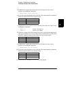
display to the limit mode. When the display is in the limit mode, program the
current to the maximum programmable value and the voltage to the full-scale
value (see Table 3-2).
3
Set the electronic load to transient operation mode between one half of the
output's full scale value and the output's full scale value at a 1 kHz rate with
50% duty cycle.
4
Set the the oscilloscope for ac coupling, internal sync, and lock on either the
positive or negative load transient.
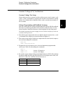
5
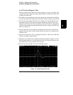
Adjust the the oscilloscope to display transients as shown in Figure 3-2. Note
that the pulse width (t
2
-t
1
) of the transients at 15 mV from the base line is no
more than 50
m
sec for each of the three outputs.
6
Repeat steps (1) through (5) for the remaining outputs.
Figure 3-2. Transient Response Time


Find Your Products By Category
- Household Appliance
- Power Tools
- Computer Equipment
- Automotive
- TV and Video
- Outdoor Cooking
- Marine Equipment
- Kitchen Appliance
- Fitness & Sports
- Lawn and Garden
- Baby
- Laundry Appliance
- Personal Care
- Home Audio
- Photography
- Video Game
- Portable Media
- Musical Instruments & Equipment
- Communications
- Car Audio and Video
Please Login
