
0
Owner's of the Agilent Technologies Welding System Agilent Technologies Welding System gave it a score of 0 out of 5. Here's how the scores stacked up:


Chapter 3
Calibration Procedures
Measurement Techniques
45
3
Measurement Techniques
Setup for Most Tests
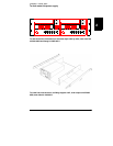
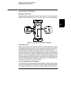
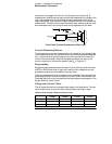
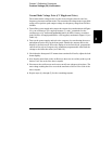
Most tests are performed at the front terminals as shown in the following figure.
Measure the dc voltage directly at the (+) and (-) terminals on the front panel.
Figure 3-1. Performance Verification Test Setup
Electronic Load
Many of the test procedures require the use of a variable load resistor capable
of dissipating the required power. Using a variable load resistor requires that
switches be used to connect, disconnect, and short the load resistor. An
electronic load, if available, can be used in place of a variable load resistor and
switches. The electronic load is considerably easier to use than load resistors.
It eliminates the need for connecting resistors or rheostats in parallel to handle
power, it is much more stable than carbon-pile load, and it makes easy work
of switching between load conditions as is required for the load regulation and
load transient response tests. Substitution of the electronic load requires minor
changes to the test procedures in this chapter.
General Measurement Techniques
To achieve best results when measuring load regulation, peak to peak voltage,
and transient response time of the power supply, measuring devices must be
connected through the hole in the neck of the binding post at (A) while the


Find Your Products By Category
- Household Appliance
- Power Tools
- Computer Equipment
- Automotive
- TV and Video
- Outdoor Cooking
- Marine Equipment
- Kitchen Appliance
- Fitness & Sports
- Lawn and Garden
- Baby
- Laundry Appliance
- Personal Care
- Home Audio
- Photography
- Video Game
- Portable Media
- Musical Instruments & Equipment
- Communications
- Car Audio and Video
Please Login
