
0
Owner's of the Agilent Technologies Portable Generator Agilent Technologies Portable Generator gave it a score of 0 out of 5. Here's how the scores stacked up:


Chapter 4 Theory of Operation
Power Mesh and Control
92
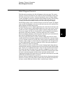
Power Mesh and Control
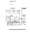
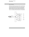
Refer to the schematics shown on page 129.
For the power mesh and control circuit, the preregulator which is controlled
by the phase control circuits is added ahead of the series pass transistor to
minimize the power dissipated at the series pass transistor by controlling the
dc level across the input filter capacitor, depending on the output voltage.
For the dual range of output, a controlled transformer tap switching is used.
It is accomplished by two SCR and one bridge diode and the SCR control circuit
in the power circuit; CR17, CR19, and CR44. By turning on or off the SCR, these
circuits allow the input capacitors (C39, C46, and C74) to charge to one of two
discrete voltage levels, depending on the output voltage required. When all
SCR’s are not fired, the bridge diode conducts and the lowest voltage of two
discrete voltage levels is developed across the input filter capacitors.
The SCR control circuit determines whether SCR is to be fired by monitoring
the output voltage and comparing this value against internally derived
reference levels.
The series pass transistor is part of the feedback loop which consists of the
driver and the Constant Voltage/Constant Current error amplifier. This
feedback loop provides ‘’fine and fast’’ regulation of the output while the
feedback loop which is controlled by transformer tap switching handles large,
relatively slow, and regulation demands.
The series pass transistor is made to alter its conduction to maintain a constant
output voltage or current. The voltage developed across the current sampling
resistors is the input to the constant current error amplifier. The constant
voltage error amplifier obtains its input from differential amplifier which
senses the output voltage. Any changes in output voltage or current are
detected and amplified by the constant voltage or constant current error circuit
and applied to the series pass transistor in the correct phase and amplitude to
counteract the change in output voltage or current.


Find Your Products By Category
- Household Appliance
- Power Tools
- Computer Equipment
- Automotive
- TV and Video
- Outdoor Cooking
- Marine Equipment
- Kitchen Appliance
- Fitness & Sports
- Lawn and Garden
- Baby
- Laundry Appliance
- Personal Care
- Home Audio
- Photography
- Video Game
- Portable Media
- Musical Instruments & Equipment
- Communications
- Car Audio and Video
Please Login
