

0
Owner's of the Agilent Technologies Portable Generator Agilent Technologies Portable Generator gave it a score of 0 out of 5. Here's how the scores stacked up:


Chapter 5 Service
To Disconnect the Output Using an External Relay
101
5
To Disconnect the Output Using an External Relay
When the output of the power supply is turned off, it is implemented by setting
the output to 0 volts and 0.02 amps. This gives a zero output voltage without
actually disconnecting the output. To disconnect the output, an external relay
must be connected between the output and the load. A TTL signal of either low
true or high true is provided to control an external relay. This signal can only
be controlled with the remote command
OUTPut:RELay
{OFF|ON}. The TTL
output is available on the RS-232 connector pin 1 and pin 9.
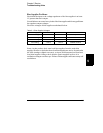
When the
OUTPut:RELay
state is ‘‘ON’’, the TTL output of pin 1 is high
(4.5 V) and pin 9 is low (0.5 V). The levels are reversed when the
OUTPut:RELay
state is ‘‘OFF’’.
Note TTL output of pin 1 or pin 9 of the RS-232 connector is available only after installing
two jumpers inside the power supply. See below for more information.
Note Do not use the RS-232 interface if you have configured the power supply to output
relay control signals. Internal components on the RS-232 circuitry may be damaged.
Installation Procedure
The assembly drawings and schematics are located in chapter 8, ‘‘Schematics’’.
1 Remove the front and rear bumpers and take off the cover (See the mechanical
disassembly drawing on page 127).
2 Install JP3 and JP4 located adjacent to the connector P5 (The JP3 and JP4 are
outlined with a circle in the component locator diagram on page 128).
A bare wire may be used.
3 Reassemble the power supply.


Find Your Products By Category
- Household Appliance
- Power Tools
- Computer Equipment
- Automotive
- TV and Video
- Outdoor Cooking
- Marine Equipment
- Kitchen Appliance
- Fitness & Sports
- Lawn and Garden
- Baby
- Laundry Appliance
- Personal Care
- Home Audio
- Photography
- Video Game
- Portable Media
- Musical Instruments & Equipment
- Communications
- Car Audio and Video
Please Login
