
0
Owner's of the Agilent Technologies Portable Generator Agilent Technologies Portable Generator gave it a score of 0 out of 5. Here's how the scores stacked up:

Chapter 3 Calibration Procedures
Constant Current (CC) Verifications
57
3
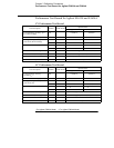
6 Record the value displayed on the controller. This value should be within the
limit of (I
O
± 5 mA).
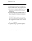
7 Program the output current to the full rated value (20.0 A)* or (7.0 A)** by
sending the command:
CURR 20.0 (E3633A)
CURR 7.0 (E3634A)
8 Divide the voltage drop (DVM reading) across the current monitoring resistor
(R
M
) by its resistance to convert to amps and record this value (I
O
). This value
should be within the limit of (20 A ± 50 mA)* or (7A ± 24 mA)**.
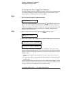
9 Readback the output current over the remote interface by sending the
command:
MEAS:CURR?
10 Record the value displayed on the controller. This value should be within the
limit of (I
O
± 35 mA)* or (I
O
± 15.5 mA)**.
CC Load Effect (Load Regulation)
This test measures the change in output current resulting from a change in the
load from full rated output voltage to short circuit.
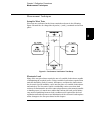
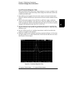
1 Turn off the power supply and connect the output to tested as shown in
Figure 3-1 with the digital voltmeter connected across the 0.01
W current
monitoring resistor (R
M
).
2 Turn on the power supply. Select the 8V/20A* or 25V/7A** range, enable the
output, and set the display to the limit mode. When the display is in the limit
mode, program the output voltage to the full rated value (8.0 V)* or (25.0 V)**
and the output current to the full rated value (20.0 A)* or (7.0 A)**.
3 Set the voltage of the electronic load to (6.0 V)* or (23.0 V)** to operate it in
constant voltage mode since a voltage drop occurs on the load wires when
(20.0 A)* or (7.0 A)** flows on the load wires. Check that the
CC annunciator
is on. If it is not, ad just the load so that the ou tp ut voltage d rops slightly. Rec ord
the current reading by dividing the voltage reading on the digital voltmeter by
the resistance of the current monitoring resistor.
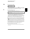
4 Operate the electronic load in short (input short) mode. Record the current
reading again by dividing the voltage reading on the digital voltmeter by the
resistance of the current monitoring resistor. The difference between the
current readings in step (3) and (4) is the load regulation current. The
difference of the readings should be within the limit of (2.25 mA)* or
(0.95 mA)**.
*For Agilent E3633A Model **For Agilent E3634A Model


Find Your Products By Category
- Household Appliance
- Power Tools
- Computer Equipment
- Automotive
- TV and Video
- Outdoor Cooking
- Marine Equipment
- Kitchen Appliance
- Fitness & Sports
- Lawn and Garden
- Baby
- Laundry Appliance
- Personal Care
- Home Audio
- Photography
- Video Game
- Portable Media
- Musical Instruments & Equipment
- Communications
- Car Audio and Video
Please Login
