
0
Owner's of the Agilent Technologies Portable Generator Agilent Technologies Portable Generator gave it a score of 0 out of 5. Here's how the scores stacked up:


Chapter 4 Theory of Operation
Block Diagram Overview
85
4
Block Diagram Overview
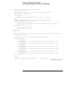
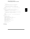
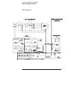
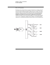
This discussion pertains to the block diagram on the next page. The power
supply’s circuitry is divided into two major blocks: the floating circuitry and
the earth referenced circuitry. All power mesh and control circuits, display
circuit, and digital circuits are contained in the floating circuitry. This circuitry
also contains the power supply’s main controller. The earth referenced
circuitry provides the interface between the user and the power supply.
The floating circuitry can be viewed in four pieces; the DAC system, the digital
logic section (floating logic), the power mesh and control section, and the front
panel (display and keyboard) section.
The floating logic receives digital signals from the earth-referenced logic and
the DAC converts them to analog signals which are sent to the power control
circuits in order to program the power supply’s output voltage and current.
The power supply can also be commanded to send measurement and status
data back to the remote interface controller and/or the VFD (vacuum
fluorescent display) display on the front panel. The data is processed and sent
back via the floating logic and earth-referenced logic.
The power mesh and control circuits contains voltage and current control
circuits which allows the power supply to operate in either the constant voltage
(CV) or constant current (CC) mode. The control circuits compare the power
supply’s output voltage or current with the programmed value and generates
a control signal which varies the conduction of the series pass transistor to
raise or lower the output as required.
The front panel circuits consist of VFD control, display high voltage drivers,
and keyboard scanning. Communication between the front panel and floating
logic circuits is accomplished through a 4-wire bi-directional serial interface.
The earth referenced circuitry uses a controller configured as a slave to the
main controller. This controller establishes external I/O communication with
the main controller through a bi-directional, optically isolated, serial
communications link. The earth referenced controller controls low-level GPIB
(IEEE-488) and RS-232 interface operation.
Separate reference and bias supplies are provided for the floating and ground
reference circuitry. The front panel operates from the floating circuitry with
its logic common different from the main controller logic common.


Find Your Products By Category
- Household Appliance
- Power Tools
- Computer Equipment
- Automotive
- TV and Video
- Outdoor Cooking
- Marine Equipment
- Kitchen Appliance
- Fitness & Sports
- Lawn and Garden
- Baby
- Laundry Appliance
- Personal Care
- Home Audio
- Photography
- Video Game
- Portable Media
- Musical Instruments & Equipment
- Communications
- Car Audio and Video
Please Login
