
0
Owner's of the Agilent Technologies Portable Generator Agilent Technologies Portable Generator gave it a score of 0 out of 5. Here's how the scores stacked up:


Chapter 3 Calibration Procedures
Measurement Techniques
50
General Measurement Techniques
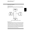
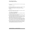
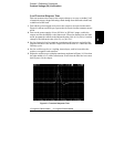
To achieve best results when measuring load regulation, peak to peak voltage,
and transient response time of the power supply, measuring devices must be
connected through the hole in the neck of the binding post at (A) while the
load resistor is plugged into the front of the output terminals at (B). A
measurement made across the load includes the impedance of the leads to the
load. The impedance of the load leads can easily be several orders of the
magnitude greater than the power supply impedance and thus invalidate the
measurement. To avoid mutual coupling effects, each measuring device must
be connected directly to the output terminals by separate pairs of leads.
Figure 3-2. Front Panel Terminal Connections (Side View)
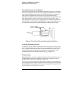
Current-Monitoring Resistor
To eliminate output current measurement error caused by the voltage drops
in the leads and connections, connect the current monitoring resistor between
the (-) output terminal and the load as a four-terminal device. Connect the
current-monitoring leads inside the load-lead connections directly at the
monitoring points on the resistor element (see R
M
in Figure 3-1).
Programming
Most performance tests can be performed from the front panel. However, an
GPIB or RS-232 controller is required to perform the voltage and current
programming accuracy and readback accuracy tests.
The test procedures are written assuming that you know how to program the
power supply either from the front panel or from an GPIB or RS-232 controller.
Complete instructions on front panel and remote programming are given in the
Agilent E3633A and E3634A User’s Guide.


Find Your Products By Category
- Household Appliance
- Power Tools
- Computer Equipment
- Automotive
- TV and Video
- Outdoor Cooking
- Marine Equipment
- Kitchen Appliance
- Fitness & Sports
- Lawn and Garden
- Baby
- Laundry Appliance
- Personal Care
- Home Audio
- Photography
- Video Game
- Portable Media
- Musical Instruments & Equipment
- Communications
- Car Audio and Video
Please Login
