
0
Owner's of the Agilent Technologies Portable Generator Agilent Technologies Portable Generator gave it a score of 0 out of 5. Here's how the scores stacked up:

Chapter 3 Calibration Procedures
Constant Voltage (CV) Verifications
54
CV PARD (Ripple and Noise)
Periodic and random deviations (PARD) in the output (ripple and noise)
combine to produce a residual ac voltage superimposed on the dc output
voltage. CV PARD is specified as the rms or peak-to-peak output voltage in the
frequency range from 20 Hz to 20 Mhz.
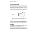
• VRMS measurement techniques:
When measuring Vrms ripple and noise, the monitoring device should be
plu gge d into the front of the termi nals at (B) in Figure 3-2 . Use the c oaxia l ca ble
and BNC female to banana plug adapter to connect the monitor device to the
power supply. To reduce the measurement error caused by common mode
noise, it is recommended that you use a common mode choke between the
cable and the BNC adapter. The common mode choke is constructed by
inserting coaxial cable into Ferrite Toroidal core. The load resistor should be
connected to the terminal at (A) in Figure 3-2. Twisted leads between the load
resistor and the power supply helps reduce noise pickup for these
measurements.
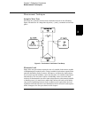
1 Turn off the power supply and connect the output to be tested as shown in
Figure 3-1 to an oscilloscope (ac coupled) between (+) and (-) terminals. Set
the oscilloscope to AC mode and bandwidth limit to 20 MHz. Connect a
resistive load (2.0
W)* or (12.5 W)** to the terminal at (A) in Figure 3-2.
2 Turn on the power supply. Select the 20V/10A* or 50V/4A** range, enable the
output, and set the display to the limit mode. When the display is in the limit
mode, program the current to the full rated value (10.0 A)* or (4.0 A)** and the
voltage to the full rated value (20.0 V)* or (50.0 V)**.
3 Check that the front panel
CV annunciator remains lit. If not lit, adjust the load
down slightly.
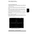
4 Note that the waveform on the oscilloscope does not exceed the peak-to-peak
limit of 3 mV.
5 Disconnect the oscilloscope and connect the ac rms voltmeter in its place
according to the VRMS measurement techniques above. The rms voltage
reading does not exceed the rms limit of 0.35 mV* or 0.5 mV**.
*For Agilent E3633A Model **For Agilent E3634A Model


Find Your Products By Category
- Household Appliance
- Power Tools
- Computer Equipment
- Automotive
- TV and Video
- Outdoor Cooking
- Marine Equipment
- Kitchen Appliance
- Fitness & Sports
- Lawn and Garden
- Baby
- Laundry Appliance
- Personal Care
- Home Audio
- Photography
- Video Game
- Portable Media
- Musical Instruments & Equipment
- Communications
- Car Audio and Video
Please Login
