
0
Owner's of the Agilent Technologies Portable Generator Agilent Technologies Portable Generator gave it a score of 0 out of 5. Here's how the scores stacked up:


Chapter 4 Theory of Operation
AC Input and Bias Supplies
87
4
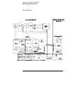
AC Input and Bias Supplies
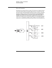
Referring to the schematic shown on pages 129 and 130, the ac mains are
connected by a fused power module. This module incorporates the functions
of mains connection, fusing, and line voltage selection (100/115/230 Vac). The
line voltage selection function of the module selects which primary winding
of power transformer is energized. The transformer secondary windings are
connected to the main pc board through connectors.
The bias supplies are consists of three sections; +5 Vdc and -5.1 Vdc for the
power circuits and floating logic; ±17.4 Vdc for the display; and +5 Vdc for the
earth referenced logic. Power-on reset signals are provided by the +5 Vdc
supply of the floating logic.
The ±17.4 Vdc for the display circuits are produced by rectifier CR8, filter
capacitors C18 and C19, and voltage regulators U12 and U16. A separate
winding of transformer provides a center tapped 6 Vrms filament supply for
the display.
The floating +5 Vdc is produced from the separate winding of transformer. The
+5_REF signal is derived from +15 Vdc supply and the TURN_ON RESET signal
is derived from +5 Vdc supply. The FAN FAIL signal is asserted when the fan
current through R20 is not detected. The TURN_ON RESET signal holds the
main controller and other logic in a reset state until the +5 Vdc logic power is
fully operational. This signal is generally active only following application of
line power to the instrument.
The +5V dc earth referenced supply is produced by rectifier CR4, filter
capacitor C23, and regulator U9. The GPIB (IEEE-488) and RS-232 computer
interfaces are powered from this supply.


Find Your Products By Category
- Household Appliance
- Power Tools
- Computer Equipment
- Automotive
- TV and Video
- Outdoor Cooking
- Marine Equipment
- Kitchen Appliance
- Fitness & Sports
- Lawn and Garden
- Baby
- Laundry Appliance
- Personal Care
- Home Audio
- Photography
- Video Game
- Portable Media
- Musical Instruments & Equipment
- Communications
- Car Audio and Video
Please Login
