

0
Owner's of the Agilent Technologies Portable Generator Agilent Technologies Portable Generator gave it a score of 0 out of 5. Here's how the scores stacked up:


Chapter 4 Theory of Operation
Floating Logic
89
4
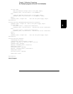
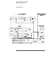
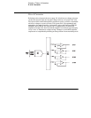
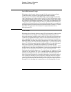
The serial register is used to send and receive serial data bytes from the main
controller to the DAC system, or to communicate with the front panel
controller. The serial register is multiplexed to these two circuits. The
transmission rate is selected to 1.5 M bits/second for the DAC system and
93.75 k bits/second for communication with the front panel controller. The
general serial interface is a 3-bit interface as shown below.
Serial data is received simultaneously as serial data is clocked out. Front panel
data is exchanged in both directions whenever a byte is sent from U20. The
input data of DAC is strobed to outputs by U19 signal SERSTB. Interrupts from
the front panel are detected by U20 and signaled to the CHINT. The main
controller FPINT signals the front panel controller that U20 has data to send.
The power supply’s calibration data are stored in a 256 x 16 bit non-volatile
electrically erasable ROM U15. This non-volatile ROM read/write data is
accessed by a 4-bit serial protocol controlled by U19.
The main controller has an on-chip 10-bit successive approximation ADC. The
FLASH input is used to sample the residual charge on the main integrating ADC
output of U25.
Port bits are also configured to measure the input power line frequency
(LSENSE). Frequencies from 55 Hz to 66 Hz are measured as 60 Hz. All other
line input frequencies are assumed to be 50 Hz.
The main controller communicates with the earth referenced controller U1
through an optically isolated (U2 and U5) asynchronous serial link. Data is sent
in an 11-bit frame at a rate of 187.5 k bits/ second. When the RS-232 interface
is selected, data is sent across the isolated link at 93.75 k bits/second. The 11-
bit data frame is configured for one start bit, eight data bits, one control bit,
and one stop bit.
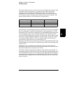
U20 Internal Signal Configuration Signals Front Panel Signals
Serial Clock SERCK XFPSK
Data OUT (send) SERDAT FPDI
Data IN (receive) SERRBK FPDO


Find Your Products By Category
- Household Appliance
- Power Tools
- Computer Equipment
- Automotive
- TV and Video
- Outdoor Cooking
- Marine Equipment
- Kitchen Appliance
- Fitness & Sports
- Lawn and Garden
- Baby
- Laundry Appliance
- Personal Care
- Home Audio
- Photography
- Video Game
- Portable Media
- Musical Instruments & Equipment
- Communications
- Car Audio and Video
Please Login
