

0
Owner's of the Aiphone Intercom System IAX-100 gave it a score of 0 out of 5. Here's how the scores stacked up:


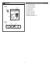
- 8 -
4-4
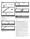
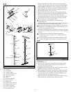
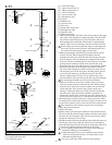
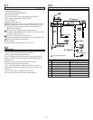
1. When the installation position is on the left as seen from the
customer side, the acoustic I/O tube can be installed unchanged
from its shipped configuration. When installing it on the right,
while referring to the diagram, reverse the left/right direction of
both slit plates of the acoustic I/O tube so that the direction of
the sound I/O opening (slit) is reversed.
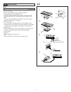
2. Open the driver unit cover, and remove from inside the driver
main unit. Attach the chassis to the glass, and then reinstall the
driver main unit and cover. The acoustic tube can also be
connected on the right side. In this case, install the driver main
unit on the reverse side. Use metal cutters to cut the joints on
the side where you wish to make the hole.
Do not forcibly rip with pliers as it could deform the
surrounding area.
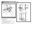
3. Clean the location where the acoustic tube will be installed and
the surrounding glass with standard cleaning fluid.
Some types of barrier glass are made of plastic, so do not use a
detergent that could damage the plastic. Also make sure it will
not affect the surrounding sealant.
4. Referring to the diagram, draw a guideline on the glass from the
top to the bottom to make sure that the acoustic tube is attached
vertically.
1. Upper and lower sections are connected together to
assemble the acoustic interface, so it is important that it is
exactly vertical.
2. Do not change the position measurements because it could
result in the length of the acoustic tube being insufficient.
English
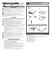
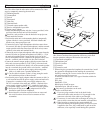
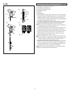
Installation preparations for the acoustic interface
[1] Fixing base
[2] Slit plate
[3] Microphone
[4] Acoustic output
[5] Acoustic tube main unit
[6] Sound I/O opening
[7] Driver unit
[8] Cover
[9] Acoustic tube holes
[10] Driver main unit
[11] Rubber seal
[12] Upper acoustic tube (2)
[13] Upper acoustic tube (1)
[14] Acoustic I/O tube
[15] Lower acoustic tube
[16] Microphone cord
4-5
English
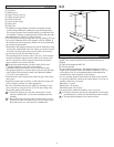
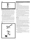
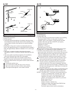
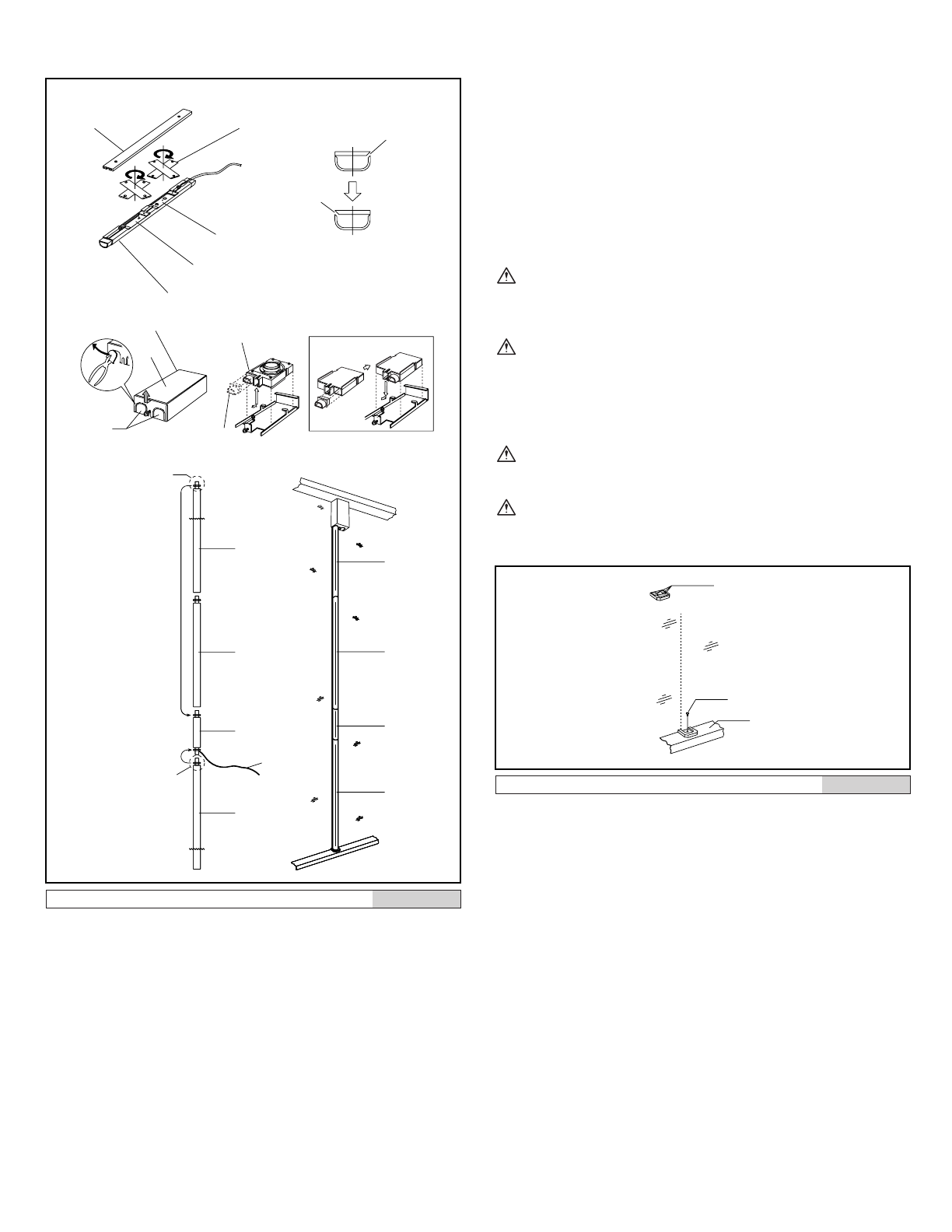
Installation of the acoustic interface (tube fixer)
[1] Double-sided tape
[2] Set screw
[3] Counter sash, etc.
1. The tube fixer secures the bottom of the lower acoustic tube.
Secure on the customer side of the counter with the screw
provided and double-sided tape.
2. Temporarily insert the acoustic tube, align the position with the
guideline, and make a pilot hole in the counter.
3. When deciding the position, it is necessary to take into account
the extra thickness caused by the double-sided tape on the tube
fixer and acoustic tube. In addition, the 2mm thickness of the
tube fixer itself must be taken into account.
4. When the position is determined, attach to the counter with the
double-sided tape, and then secure with the set screw.
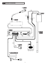
Cut
Red
Blue
Red
Blue
Blue
Red
Red
Blue
Cut
[1]
[2]
[3]
[4]
[5]
[6]
[6]
[7]
[8]
[9]
[10]
[11]
[12]
[13]
[14]
[15]
[12]
[13]
[14]
[15]
[16]
Change
Change
Not use connector
Not use connector
1
2
4
[1]
[2]
[3]
Guideline


Find Your Products By Category
- Household Appliance
- Power Tools
- Computer Equipment
- Automotive
- TV and Video
- Outdoor Cooking
- Marine Equipment
- Kitchen Appliance
- Fitness & Sports
- Lawn and Garden
- Baby
- Laundry Appliance
- Personal Care
- Home Audio
- Photography
- Video Game
- Portable Media
- Musical Instruments & Equipment
- Communications
- Car Audio and Video
Please Login
