
0
Owner's of the Aiphone Intercom System IAX-100 gave it a score of 0 out of 5. Here's how the scores stacked up:

- 7 -
English
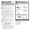
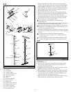
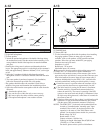
Main unit
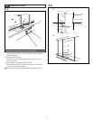
Install the main unit under the counter or desk on the operator
side. The cables from the other units will be connected at a later
stage by temporarily removing the main unit.
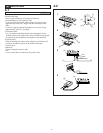
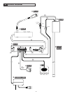
[1] Mounting bracket
[2] Counter/desk
[3] Switch
[4] Front panel
[5] Main unit
[6] Terminal block
[7] Transmit output speaker cable
[8] Receive microphone input cable
[9] Power supply adapter
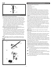
1. Install the mounting bracket with the 4 screws provided, in the
position where the main unit will be installed.
Install in a safe position so that the knobs do not project out
from under the counter.
2. Position the main unit on the mounting bracket (temporarily
tighten with the 4 screws provided), and check whether the
knobs or any other part projects out.
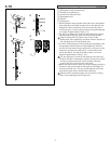
3. Connect the receive input microphone cable that comes from
the acoustic I/O tube (or optional microphone), and the transmit
output speaker cable that comes from the driver unit (or outer
speaker) to the main unit terminal block.
• Connect the receive input microphone cable that comes from the
acoustic I/O tube (or optional microphone) to R MIC [+ – E] of
the main unit terminal block. Insert the hot (red) wire of the
receive microphone into the + terminal, the ground (white) wire
into the – terminal, and the shield wire into the E terminal.
• Connect the transmit output speaker cable that comes from the
driver unit (or outer speaker) to T OUT [H C] of the main unit
terminal block. Insert the hot (black) wire of the transmit speaker
into the + terminal, the ground (white) wire into the – terminal.
1. Be sure not to short the power supply cable and speaker
cable, as it could cause a speaker malfunction.
2. Cut the cable in advance so that it is long enough to reach
the installation position of the main unit.
4. Position the power supply adapter under the counter or desk, in
a safe location between the power supply socket and main unit.
Connect the + terminal of the power supply adapter to the
DC24V + terminal of the main unit, and the – terminal of the
power supply adapter to the DC24V – terminal of main unit.
3. On power supply, take FG ( ) terminal to an earth ground.
4. Do not turn on the power supply adapter until all of the
installation work has been completed.
5. Do not install in a location exposed to heat or water, and
also avoid locations where excessive amounts of dust
accumulate.
4-3
English
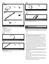
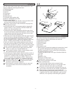
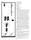
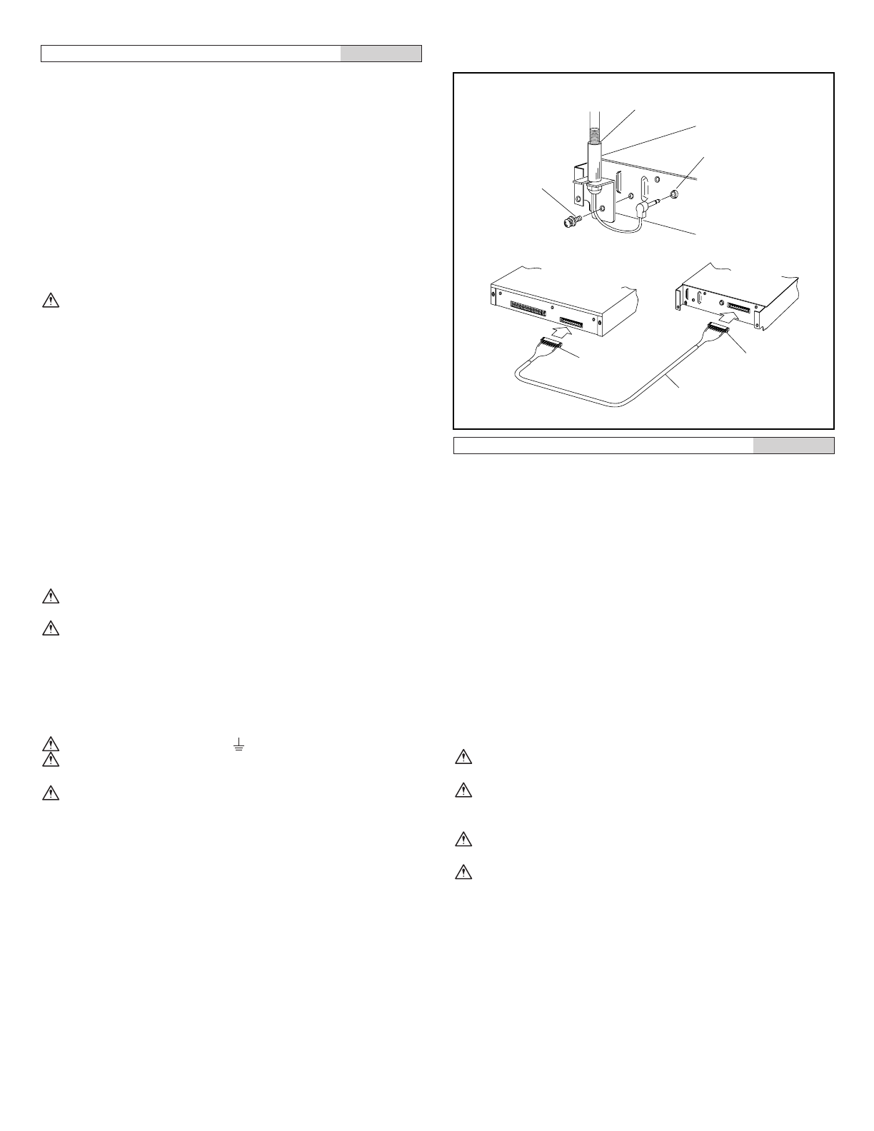
Operation unit
Position the operation unit on the counter or desk on the operator
side. Select a location where operation will be easy, and check
that the operation cable provided reaches the main unit.
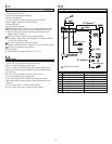
[1] Gooseneck microphone
[2] Microphone jack
[3] Screw w/washer
[4] Connector
[5] Connection cord
1. When using the gooseneck microphone for transmission, install
the gooseneck microphone before making the connections.
Install by removing the 2 screws on the rear of the operation
unit and removing the rear cover.
A headset can also be used. Use a type of headset suitable for
your needs.
Ø3.5 plug
Impedance: 32 Ω
Rated input: 40 mW or more
Maximum input: 100 mW or more
Only mono type headsets can be used.
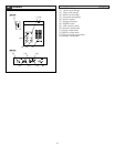
2. Connect to the main unit.
1. If you are going to make a hole in the desk for the
connection cable, make sure that it is big enough for the
connector at the end of the cable to pass through.
2. If a raceway is used on the desk to manage the wiring, be
sure to select a route that does not interfere with operation.
3. When inserting or removing the connector,hold the
connector housing and align the polarity. If excessive force
is applied to the wires, they could break or pull out of the
connector, so be especially careful during this operation.
1
2
[1]
[2]
[3]
OU-100
MU-100
[4]
[5]
[4]


Find Your Products By Category
- Household Appliance
- Power Tools
- Computer Equipment
- Automotive
- TV and Video
- Outdoor Cooking
- Marine Equipment
- Kitchen Appliance
- Fitness & Sports
- Lawn and Garden
- Baby
- Laundry Appliance
- Personal Care
- Home Audio
- Photography
- Video Game
- Portable Media
- Musical Instruments & Equipment
- Communications
- Car Audio and Video
Please Login
