

0
Owner's of the Aiphone Intercom System IAX-100 gave it a score of 0 out of 5. Here's how the scores stacked up:

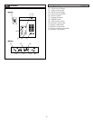
- 10 -
4-8
English
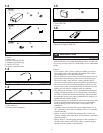
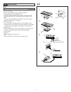
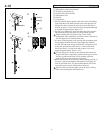
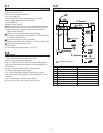
Installation of the acoustic interface (acoustic I/O tube)
[1] Fixing base of the acoustic I/O tube
[2] Fixing base of the lower acoustic tube
1. Remove the fixing base from the acoustic I/O tube main unit.
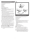
2. Attach double-sided tape to this fixing base. With the red label
on the upper side, position the bottom of the fixing base of the
acoustic I/O tube so that it makes contact with the top of the
fixing base of the lower acoustic tube, which is already attached
to the glass. Attach the fixing base of the acoustic I/O tube to
the glass by aligning it with the guideline and making sure
there is no gap between it and the lower fixing base, and that
there is no misalignment to the left or right.
The acoustic tubes should be fully connected, so it is
important that the upper and lower fixing bases are installed
with no misalignment to the left or right.
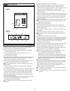
3. After attachment, insert while aligning the connection ridge of
the acoustic I/O tube main unit and the connection groove of
the fixing base. Try to fix while pushing downwards (the slide
distance is approximately 10mm). Push down to the boundary
of the upper and lower fixing bases, and check that it can be
fully fixed. After checking,remove the acoustic I/O tube main
unit.
Do not apply excessive force, as the adhesive power of the
double-sided tape will not yet have reached its full strength.
4-9
English
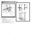
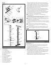
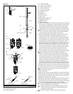
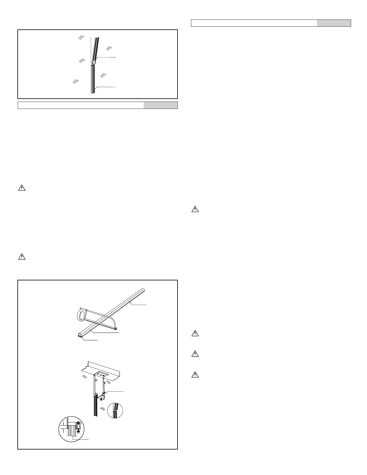
Installation of the acoustic interface (upper acoustic tube)
[1] Used side (blue label side)
[2] Discarded side (red label side)
[3] Red label
[4] Driver unit chassis
[5] Fixing base
1. Measurements and cutting
•Align the position of the top of the fixing base of the acoustic
I/O tube that has already been installed with the position of the
blue label side of the upper acoustic tube. Decide the cutting
position by aligning the fixing base with the position shown by
the driver unit tube top position diagram. The tube top position
diagram shows the ideal position for the top of the tube after
cutting.
•When cutting the upper acoustic tube, make sure that the side
that is discarded is the red label side. Do not cut the blue label
side because it is the tube connection side (the end that should be
cut is opposite for the upper and lower tubes).
•Install the removed packing on the top of the acoustic I/O tube.
•When using only one acoustic tube on the upper side (1 m or
less), the removed tube connector is not used. When using 2 or
more tubes, the tube connector and packing (of the 1 m acoustic
tube that is not cut) are used unchanged.
•After cutting, use a file or sandpaper to smooth the ends of the
acoustic tube main unit and fixing base. After the cut surface is
completely smooth, it is connected to the driver unit with the
rubber seal.
The red label side of the upper acoustic tube is discarded.
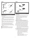
2. Attachment
•Attach double-sided tape to the outer surface (flat surface) of the
fixing base.
•Attach double-sided tape to the fixing base of the upper acoustic
tube. With the blue label on the lower side, position so that it
makes contact with the top of the fixing base of the acoustic I/O
tube that has already been installed. Attach to the glass by
making sure there is no misalignment to the left or right and that
it is aligned with the vertical guideline. If the top is aligned with
driver unit chassis in the tube top position diagram shown on this
page,then the position is correct.
•After attachment, insert the acoustic tube main unit into the
fixing base, and check the fixing condition while pushing it
downwards (the slide distance is approximately 10 mm). After
checking, remove the acoustic tube main unit. The acoustic tube
main unit could slip and fall when checking the fixing condition,
so do not let go of it.
1. The double-sided tape can be seen from the operator side,
so when attaching make sure it does not protrude from the
edges and is not bent.
2. The acoustic tubes should be fully connected, so it is
important that the upper and lower fixing bases are installed
with no misalignment to the left or right.
3. Do not apply excessive force, as the adhesive power of the
double-sided tape will not yet have reached its full strength.
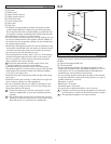
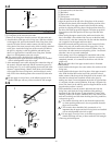
3. Tube top position diagram
[1]
[2]
Guideline
10mm
1
2
3
[1]
[2]
[3]
[4]
[5]


Find Your Products By Category
- Household Appliance
- Power Tools
- Computer Equipment
- Automotive
- TV and Video
- Outdoor Cooking
- Marine Equipment
- Kitchen Appliance
- Fitness & Sports
- Lawn and Garden
- Baby
- Laundry Appliance
- Personal Care
- Home Audio
- Photography
- Video Game
- Portable Media
- Musical Instruments & Equipment
- Communications
- Car Audio and Video
Please Login
