

0
Owner's of the Aiphone Intercom System IAX-100 gave it a score of 0 out of 5. Here's how the scores stacked up:

- 13 -
4-12
English
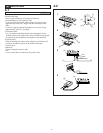
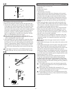
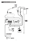
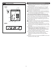
Outer microphone/speaker
[1] Raceway
[2] Optional microphone
[3] Outer speaker
1. Attach the optional microphone with double-sided tape along
the architectural sash. Clean the surface before attaching. Use a
strong industrial double-sided tape that can attach aluminum
and glass.
• Examine the wiring route in advance and determine the best
layout. The appropriate position is at the height of the customer's
head, and approximately 300mm to 400mm (12-16") to the right
or left.
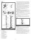
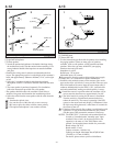
2. Splice the 2-conductor shielded cable from the optional
microphone with the 2-conductor shielded cable from the main
unit.
3. The outer speaker is purchased separately. For installation,
follow the instructions provided with your speaker.
• The speaker should be above the customer's head. Select a
suitable wiring route and determine the installation position.
4. Splice the cable from the outer speaker with the cable from the
main unit.
1. Insulate the spliced wires.
2. Lay out the wires within the sash, or use a raceway.
3. Be sure to splice the cables with the correct polarity.
4. The optional microphone is not weather resistant.
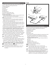
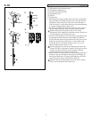
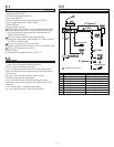
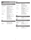
Options
[1] Paging speaker
[2] Terminal block
[3] Sensor ISE-100
1. Use the instructions provided with the product when installing
the paging speakers. There are many types of speakers
available, such as wall speakers, ceiling speakers and horn
speakers. Select the type most suitable for your paging
broadcast area and your needs.
Impedance: 4 to 8 Ω
Rated input: 3 W or more
Maximum input: 6 W or more
Be sure not to short the speaker cable and the power supply
cable (24V), as it could cause a speaker malfunction.
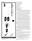
2.
Install the sensor under the counter on the customer side or on the
upper section of the wall with the 2 screws provided. There are screw
holes in the handle of the sensor. Insert the sensor output cable (2-
conductor shielded cable) into the STBY [+ SW -] terminal of the
main unit terminal block, making sure that the polarity is correct.
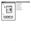
1. Install the sensor in a position where the customer will be
sure to enter the detection area: approximately 2m, 6'6".
2. The initial sensitivity setting for the sensor is maximum.
Turn the sensitivity volume knob counterclockwise to
reduce the sensitivity. The sensor is operating if the LED
(green) on the sensor main unit display is illuminated. After
an object stops being detected, it takes about 10 seconds for
the sensor to turn off.
3.
If the lens of the sensor is dirty or dusty it could interfere with
operation. It is also possible that children may play around
with the sensor. Take preventative measures as necessary.
NOTES: The STBY [SW –] in the main unit terminal block can
be used as a communication "normally open" input
terminal. If the switch is in the closed position, the
operation is the same as if the TALK button were
pushed. Use the method most suitable for your needs.
Rated voltage: DC 30 V
Rated current: 15 mA
Contact resistance: 100 Ω or less
Cable layout length: Maximum 20m,65'(Ø0.65 mm
(22AWG) to 1.2 mm (16AWG))
For details, please contact your local distributor.
English
4-13
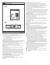
to Main unit
to Main unit
from
External mic.
from
External speaker
(
-
) White
(E) Shield
(+) Red
(+) Black
(
-
) White
12
34
[1]
[2]
[3]
1
2
[3]
[2]
[1]
[2]
Volume


Find Your Products By Category
- Household Appliance
- Power Tools
- Computer Equipment
- Automotive
- TV and Video
- Outdoor Cooking
- Marine Equipment
- Kitchen Appliance
- Fitness & Sports
- Lawn and Garden
- Baby
- Laundry Appliance
- Personal Care
- Home Audio
- Photography
- Video Game
- Portable Media
- Musical Instruments & Equipment
- Communications
- Car Audio and Video
Please Login
