
0
Owner's of the JVC Security Camera JVC Security Camera gave it a score of 0 out of 5. Here's how the scores stacked up:
3
Image Adjustment
Adjust images by watching them on the monitor.
* The illustration of the camera directly mounted on the ceiling is used.
The same procedures are performed when mounting the camera on
the wall with the cables pulled out.
Note
• Before touching the camera body, make sure you touch the metal
surface of the [MONITOR] terminal first to discharge any static
electricity from your body.
Otherwise, static electricity may cause the camera to malfunction.
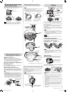
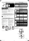
Adjust the shooting direction of the camera
1
Connect a test monitor to the [MONITOR] terminal.
2 After checking that the [MONITOR] selection
switch is set to "NTSC", press the [FOCUS
ASSIST] button.
75 Ω
termination
Test
monitor
[MONITOR] terminal
Memo
• The camera has the 16:9 aspect ratio. If the test monitor has the 4:3
aspect ratio, the camera image is converted into the 4:3 ratio and
displayed.
• Set to "NTSC" when connecting to an NTSC monitor, or set to "PAL"
when connecting to a PAL monitor, then hold down the [RESET]
button for approximately three seconds to reboot. While the camera
is rebooting, the [STATUS] indicator lights up orange.
•
If you keep pressing the [RESET] button for more than 5s, the camera
enters the Service mode. Do not press this button for more than 5s.
3 Adjust the shooting direction of the camera
Before you start, remove the light-blue protection tape.
Adjust the pan, tilt and rotation controls of the cameras to face the
lens towards the subject.
Note
• Moving the pan, tilt or rotation beyond the adjustment range may
damage this unit.
• As the tilt and rotation range of this unit is wide, part of this unit may
be reflected in the shooting screen depending on the field angle and
direction.
• Do not hold the lens section when adjusting the direction of pan, tilt
or rotation. The lens section may be damaged if you apply excessive
force to it.
Pan: ± 175°
Tilt: ± 80°Rotation: ± 100°
Shooting direction mark
[RESET] button
Rotation
knob (two
locations)
Tilt fastening screw
[STATUS] indicator
[MONITOR] selection switch
NTSC
[FOCUS
ASSIST]
button
PAL
Protection
tape
Memo
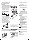
Adjust the field angle and focus
1 Adjust the zoom ratio.
Loosen the fastening screw of the zoom adjustment ring, then
move the ring to the right and left to adjust the zoom ratio. After
completing the adjustment, tighten the setscrew.
Note
• Applying force to the zoom adjustment ring while adjusting the
image size may result in damage.
Moving the zoom adjustment ring beyond its adjustable range
may cause the performance of this camera to deteriorate.
2 Roughly adjust the focus.
1 Lift the focusing gear control, release the catch from position A
and insert it into position B to disengage the gear.
Note
•
If you open the gear beyond position B, the gear shaft is
released from the bearing (C in the figure on the left) to prevent
it from being damaged. In this case, correctly re-insert the shaft
into bearing A (the original position).
VN-H257VPU camera
2 Rotate the lens section at the tip to roughly adjust the focus.
2
Lens section
Note
• Do not hold the lens section when adjusting the direction of the
camera. The lens section may be damaged if you apply force to
it. Also, exercise care not to leave your finger prints on the lens
when you rotate the lens section.
3 Return the catch of the focus adjustment gear to B position A
shown in the diagram, and then return the focus adjustment
gear to its original position.
VN-H237VPU camera
2 Loosen the focusing ring setscrew and roughly focus the image
by rotating the ring to the right or left.
3 Return the catch of the focus adjustment gear to B position A
shown in the diagram, and then return the focus adjustment
gear to its original position.
3 Finely adjust the focus.
VN-H257VPU camera
1
Connect the camera to a computer, and open the Built-in Viewer.
• For details about computer settings and methods for
connecting the camera to a computer, refer to “Instructions (IP
Address Settings)”.
2 Select “Day Focus Adjust” from the “Focus” page in “Advanced
Settings”.
• The focus position is automatically adjusted.
• For details on focus, refer to “Instructions (Setting)” on the
supplied CD-ROM.
• You can also adjust the focus after mounting the dome cover.
VN-H237VPU camera
1 Press the [FOCUS ASSIST] button.
• The camera enters Focus Assist mode, and [STATUS]
indicator flashes green and orange alternately.
• The image is sharpened with the opening of the aperture.
2 Finely adjust the camera focus by rotating the focus adjustment
gear knob to the right or left.
3 Rotate the focus adjustment gear knob for approximately one
base pitch in the direction of the arrow shown in the figure.
•
This is to correct the focus shift when mounting the dome cover.
4 Remove the protective sheet of the dome cover, and check the
camera focus by holding the dome cover over the lens.
•
After checking, replace the protective sheet on the dome cover.
5
Tighten the setscrew of the focus adjustment ring and fix the focus.
6 Press the [FOCUS ASSIST] button.
• The Focus Assist mode will be released.
• [The STATUS] indicator lights up green.
Note
• It may be difficult to acquire focus automatically when shooting
the following places.
– Too bright places.
– Too dark places.
– Places where brightness always changes. (e.g. a light is
flickering; people are passing by in front of the camera.)
– Places where there is little contrast of brightness.
– Places where there are repeating patterns of vertical stripes.
Memo
• The focus position can be manually adjusted by using the Built-
in Viewer installed on your computer connected to the camera.
(☞ “Instructions (Setting)”) Resort to this method if it is difficult
to acquire focus automatically.
☞ Continued overleaf
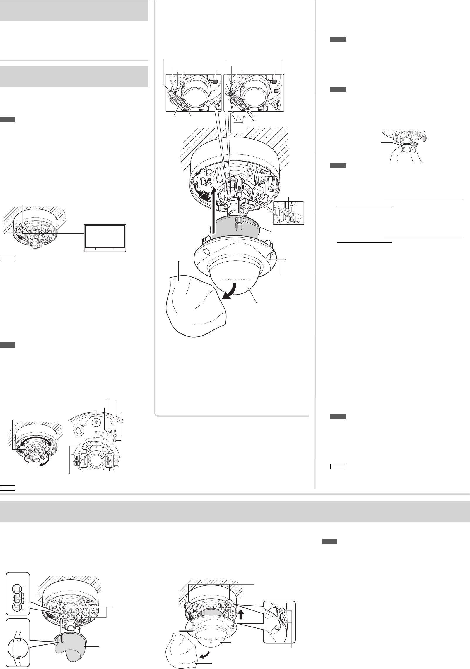
Mount the dome cover
Mount the inner dome
Engage the inner dome slot with the projection, and mount
the dome by rotating it in the direction of the arrow. Press
the inner dome in until you hear the click of the catch.
Catches
(two locations)
Inner
depression
Protruding
part
Inner dome
Mount the dome cover and remove
the dome cover protective sheet
Align the position aligning marks (three locations) on
the camera body and the dome cover, mount the dome
cover and secure it using the supplied wrench.
Position aligning mark
(three locations)
Dome cover
Dome cover protective sheet
Position aligning mark
Turn on the power
After all connections and installations are completed,
turn on the power of the unit. When the camera is
booting, the [STATUS] indicator lights up orange. It lights
up green after booting.
When you mount the dome cover, make sure that no cables are connected to the [MONITOR] terminal.
Note
• Before installing the dome cover, make sure that silica gel (supplied)
is placed inside.
• Mount the dome cover firmly. If it is not fixed securely enough, the
moisture inside the camera increases, fogging the inside of the cover
or causing the cover to fall off.
• If you remove the dome cover after installing it, the field angle may
shift. If the field angle has shifted, adjust the focus and the field
angle again.
• Pay attention to the fall prevention wire so that it will not be caught
between the dome cover and the camera. Otherwise, dust proofing
and waterproofing may not work correctly.
Catches
* The VN-H257VPU camera is shown in the illustration.
BA BA
Knob
CatchesZoom
adjustment ring
Zoom
adjustment ring
Focusing ring
C
Focus
adjustment gear
C
Focus adjustment gear
One base
pitch
Tilt fastening
screw
Protruding part
Wrench
(supplied)
Dome cover
Dome cover
protective
sheet
VN-H257VPU camera VN-H237VPU camera
Knob
• Rotate the lens in the pan, rotation and tilt directions ± 175°, ± 100°
and ± 80° respectively from the position aligned with the camera's
shooting direction mark, pan center mark and rotation center mark.
Be sure to hold the rotation control and adjust the rotation without
holding the lens section.
• When you mount the camera body, align the shooting direction mark
within the shooting direction.
• After adjusting the field angle, tighten the tilt fastening screw to secure
the camera so that its field angle does not go out of alignment.
EN_VN-H257VP_001D_Non-Mask.indb 3EN_VN-H257VP_001D_Non-Mask.indb 3 5/24/2012 2:59:09 PM5/24/2012 2:59:09 PM


Find Your Products By Category
- Household Appliance
- Power Tools
- Computer Equipment
- Automotive
- TV and Video
- Outdoor Cooking
- Marine Equipment
- Kitchen Appliance
- Fitness & Sports
- Lawn and Garden
- Baby
- Laundry Appliance
- Personal Care
- Home Audio
- Photography
- Video Game
- Portable Media
- Musical Instruments & Equipment
- Communications
- Car Audio and Video
Please Login
