
0
Owner's of the JVC Security Camera JVC Security Camera gave it a score of 0 out of 5. Here's how the scores stacked up:
2
☞ Continue to next page
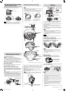
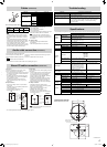
Remove the dome cover and the inner dome.
1
2
Knob (two
locations)
Dome cover
Fall prevention
wire
Wrench (supplied)
Inner dome
Memo
• When you remove the dome cover, use the supplied wrench.
• To remove the inner dome, turn it 45 degrees and grasp the inner
dome near the catches (two locations). It will come off easily.
Mounting the Camera
Note
Read before starting work.
• Special skills are required to install this unit.
• Install this unit on a location that is strong enough to hold it.
• Use the appropriate attachment screws and tighten them securely.
• Make sure you turn off the power supply to the device before starting work.
• When you attach the camera body to the ceiling, be sure to wear
safety goggles to protect your eyes from falling objects.
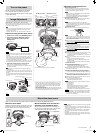
Opening a hole (approx. Φ 30 mm) on
the ceiling or wall
Open a hole (approx. Φ 30 mm) in the ceiling or wall,
and pull the cables out of the hole.
Attach the fall prevention wire
To attach the fall prevention wire, remove the attachment
screws of the fall prevention wire on the bottom of the camera
body (the fall prevention wire and cables are not provided).
Note
• Attach the fall prevention wire to a sufficient strong location such as
the ceiling or wall.
• Mount the fall prevention wire using an attachment screw.
•
Take note of the length and strength of the fall prevention wire. Use wire
made of insulated material. Make the wire length as short as possible.
• Use the appropriate attachment screws and tighten them securely.
• Use stainless steel attachment screws. If you use stainless steel
screws, apply rust-proofing, for example, by painting them after
installation. Tighten the screws securely so that the unit will not fall off.
Camera
body
Approx. Φ 30 mm
Fall prevention wire (Not provided)
Fall prevention wire
8 mm
2 mm
Shooting direction mark
4.3 mm or less
Φ 12 mm or less
Φ
4.1 to
Φ
6.5 mm
Waterproofing
Filling the dust hole and the mounting holes (two
locations) with waterproof seal material (GE silicon).
Waterproof treatment (three locations)
* This illustration does not show
the inside of the camera body
for convenience of explanation.
After adjusting images, place the silica gel in the location
shown in the diagram below.
Rug plate
* Fix the silica gel
so that it will not
fall off.
Silica gel
Silica gel
Insertion space
Note
• Take silica gel out of the aluminum pack, place in the space for
inserting silica gel inside the camera body, and fix it using the rug
plate.
• Completely plug the duct hole and the mounting holes. Water and
moisture may get inside and fog the lens and dome cover.
• If it is raining when you install the unit, exercise care to prevent any
rain from entering.
• Be sure to place silica gel. If you use a type of silica gel other than
that supplied with this unit, the camera lens and the dome cover may
become fogged.
• When you open the dome cover for repair or maintenance, replace
the silica gel.
• Correctly waterproof all the cables using waterproof tape (adhesive).
• If you do not adjust the field angle (
☞ Page 3) immediately after
installing the camera, place the silica gel when adjustment is
finished. The effects of silica gel wear off if it is exposed to air for a
long period of time.
• Apply seal materials to or caulk the gap between the camera and the
ceiling or wall.
Secure the camera to the ceiling or wall
After connecting the cables, attach the camera to the ceiling (or
on the wall).
Use the attachment screw (approx. Φ 4 mm) to secure the
camera body to the ceiling or wall.
When you mount it, align the shooting direction mark with the
range you want to shoot.
Note
•
Check to ensure that there is no gap between the ceiling and the camera.
• Ensure that neither the cables nor the fall prevention wire of the
dome cover are tucked in.
* This illustration does not show
the inside of the camera body for
convenience of explanation.
Shooting direction mark
Mounting
hole
Attachment screw
(Prepared by customer)
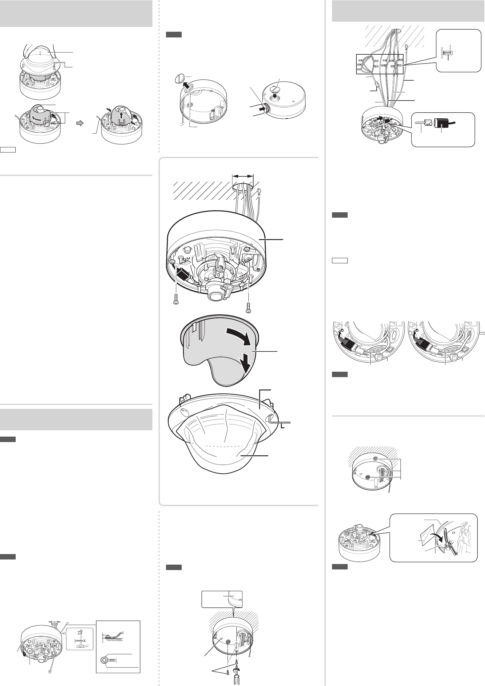
Using the duct hole on the side
Loosen the fastening screws (M3 x 6 mm) and remove the
plug for the duct hole using a flat-blade screwdriver.
Note
• When you insert a pipe, do not insert it deeper than 12 mm. Inserting
it further may damage the inside of this unit.
• If you install the unit, using the duct hole on the bottom or on the side,
wrap seal tapes around the connecting parts (the point where the thread
of the duct hole and the screw hole meet) of the duct at least twice.
Plug for duct hole
Setscrews
Seal tape
Plug for duct hole
* This illustration does not show
the inside of the camera body for
convenience of explanation.
* Place the duct hole plug that you
removed into the duct hole at the
bottom of the camera.
Alarm cable
(VN-H257VPU)
Fall prevention wire
Power cable (VN-H257VPU)
Soldering or crimping
Wrapping insulation tapes
LAN cable
connector
LAN cable
Audio cable (VN-H257VPU)
LAN cable
Ferrite core
(VN-H257VPU)
Connect the AC 24 V power cable, alarm cable, and audio cable to
their respective connectors by crimping them or soldering them.
Wrap unused connectors and the ends of unused cables with insulation
tape and waterproof tape.
Make sure the LAN cable is completely inserted into the connector.
After confirming the connection, waterproof it by wrapping it with
waterproof tape.
Attach the supplied ferrite core only to the Alarm I/O cable. (VN-H257VPU)
Securely attach the fall prevention wire to a section that is sufficiently
strong (a slab or channel).
Note
• Always use the AC 24 V power supply that is insulated from the
primary power circuit. An autotransformer or similar single winding
transformer may fail or damage the camera.
• If you use both the AC 24 V power cable and the PoE-based LAN
cable simultaneously, the camera may fail. Always supply power
using either method.
Memo
• Put the cables into the hole that you opened on the ceiling or wall
after connecting.
Connecting the LAN cable
When using the duct hole at the bottom of the base or on
the side, attach the LAN cable as follows.
Using the duct hole at the
bottom of the base
Using the duct hole
on the side
SD card slot
Mounting hole
for a screw
SD card slot
Mounting hole
for a screw
Note
• Make sure that the LAN cable does not cover the SD card slot.
• Writing data to and reading data from an SD card is not currently
supported. Do not insert an SD card.
• When connecting the LAN cable, keep it away from the mounting
hole for a screw.
Cabling
Removing the dome cover
and the inner dome
Inner
dome
Wrench
(supplied)
Dome cover
protective
sheet
Camera
body
Dome
cover
Approx. Φ 30 mm
* The VN-H257VPU camera is shown in the illustration.
EN_VN-H257VP_001D_Non-Mask.indb 2EN_VN-H257VP_001D_Non-Mask.indb 2 5/24/2012 2:59:08 PM5/24/2012 2:59:08 PM


Find Your Products By Category
- Household Appliance
- Power Tools
- Computer Equipment
- Automotive
- TV and Video
- Outdoor Cooking
- Marine Equipment
- Kitchen Appliance
- Fitness & Sports
- Lawn and Garden
- Baby
- Laundry Appliance
- Personal Care
- Home Audio
- Photography
- Video Game
- Portable Media
- Musical Instruments & Equipment
- Communications
- Car Audio and Video
Please Login
