
0
Owner's of the JVC Security Camera VN-H137U gave it a score of 0 out of 5. Here's how the scores stacked up:
4
Specifications
*
The specifications and appearance of this unit are subject to change for purposes of improvement without prior notice.
VN-H57U VN-H37U VN-H137U
Camera
section
Image sensor 1/3-inch Square-Pixel Progressive Scan CMOS (elementary color filter)
Effective pixels
Approximately 2,120,000 pixels
1944 (H)×1092 (V)
Lens mount CS mount –
Approved lens Refer to our catalog. –
Minimum illuminance
of subject
(F1.2, 50 % , AGC High, 1/30 s)
Color: 0.3 lx (typ.)
Black and White : 0.03 lx (typ.)
(50 %,AGC High,1/30 s)
Color: 0.3 lx (typ.)
Easy Day and Night :
0.25 lx (typ.)
Monitor output
75 Ω, 1.0 Vp-p
NTSC or PAL (switch selectable)
Audio input
Input
mini-jack (
Φ
3.5 stereo R ch),
can connect to a microphone
that has a plug-in power system
–
Reference voltage DC2.47 V(typ.) –
Impedance 2.2 kΩ(typ.) –
Audio output
Line OUT (200 Ω, Max 1.9 Vp-p)
mini jack (Φ3.5 stereo L ch)
–
Network
output
Image compression
format
JPEG, H.264 High Profile, H.264 Baseline Profile, MPEG-4
Frame size
1920 × 1080
1280 × 960
1280 × 720
640 × 480
640 × 360
320 × 240
Audio compression
formats
μ-Law (64 kbps), AD/DA 16
bits, Fs = 8 kHz, monaural
–
Network interface
RJ-45
100BASE-TX/10BASE-T/FULL/HALF/Auto-negotiation enabled
Alarm input
No-voltage a contact input, PNP
open collector input, low level,
latch/momentary (500 msec or
longer) (1 mA circuit current at
low level, and 3.3 VDC applied
voltage at high level)
–
Alarm output
NPN open collector -output (12
VDC safe excitation voltage, and
30 mA allowable sink current)
–
Alarm record 16 MB
Lens
Focal length – f = 2.8 to 10.5 mm
Maximum aperture
ratio
–
F1.2 (f = 2.8 mm) to F2.6
(f = 10.5 mm)
Aperture range – F1.2 to F360
Zoom ratio – 3.75 x
LAN
standards
Standards Compliant with IEEE802.3, IEEE802.3u and IEEE802.3af
Communication
protocol
TCP/IP, UDP/IP, FTP, ICMP, ARP, DHCP, SNTP, HTTP, SMTP, RTP, RTSP, IPv4, IPv6,
DSCP, HTTPS, SNMP
General
Power supply
voltage
AC24 V 50 Hz/60 Hz, or
PoE(DC-48 V)
PoE(DC-48 V)
Current consumption
AC24 V 0.5 A, or PoE 150 mA
(7.2 W)
120 mA
Ambient
temperature
-10 °C to 50 °C (Operation)
0 °C to 40 °C (Recommended)
Ambient humidity 20 %RH to 90 %RH (without condensation)
Mass Approx. 360 g Approx. 340 g Approx. 390 g
Cables
Symptom Causes and Countermeasures
Movement of network image is
not smooth
If the monitor image output is turned ON, a lower frame rate is set for
network images.
If you turned the monitor image output to OFF, set the frame rate
again.(
☞ “Instructions (Setting)” - “Internet Explorer Setting” -
“Encoding Page”)
•
•
No monitor image is output.
The image output may be turned Off on Internet Explorer.
Check the monitor output setting.
The external mic sound is not heard.
Check the MIC connection.
Is the audio setting turned off? (
☞
“Instructions (Setting)” - “Audio Page”)
•
•
Lens is out of focus
Is the focus adjustment gear engaged? Check the location of the catch. (VN-H137U)
Make sure that the lens is compatible with a CS mount.(VN-H57U/VN-H37U)
After initializing the back focus position(
☞
“Instructions (Setting)” - “Focus Page”),
perform focus adjustment again. (VN-H57U)
Rotate the back focusing ring to adjust the focus.(VN-H37U)
•
•
•
•
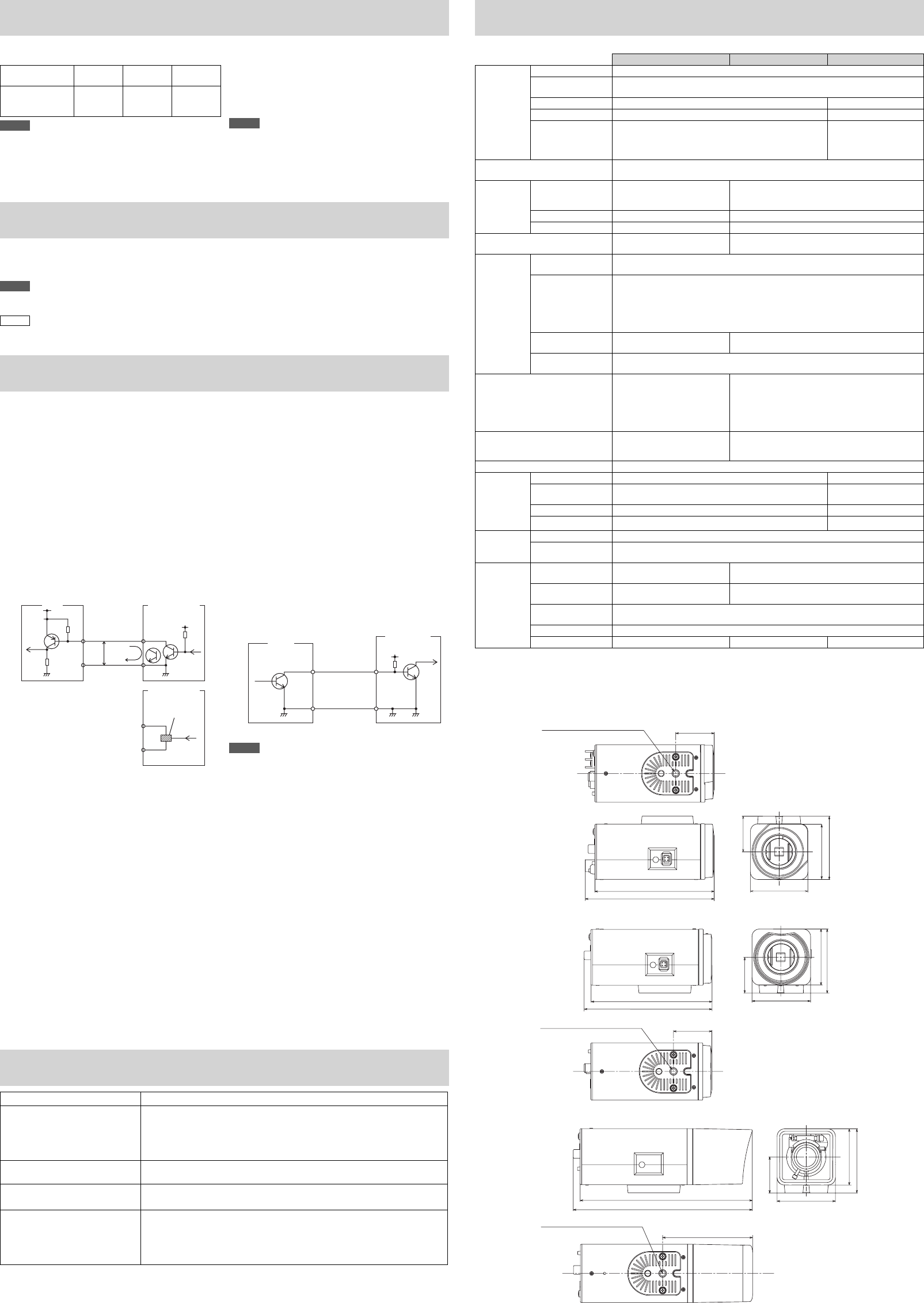
VN-H57U External dimensions (unit: mm)
55
53
61
34
123.5
114
37
Screw hole for the camera-mounting
1/4-20UNC
VN-H37U External dimensions (unit: mm)
55
53
61
34
121
37
114
Screw hole for the camera-mounting
1/4-20UNC
VN-H137U External dimensions (unit: mm)
55
34
85
162
170
53
61
Screw hole for the camera-mounting
1/4-20UNC
LST1230-001D
Troubleshooting
Audio cable connection
(VN-H57U)
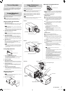
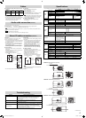
Alarm I/O cable connection (VN-H57U)
Alarm input
Connect an infrared sensor, door sensor, metal
sensor, a manual switch or other device.
To avoid noise entering the internal circuit, enter the
non-voltage contact signal in the Alarm IN terminal.
Do not supply voltage.
The alarm can be set to be activated during close
contact (MAKE) or during open contact (BREAK)
can be set from the menu.
The alarm signal should last for at least 500 msec. If
the alarm signal is short, it may not be recognized.
Input conditions
Connect non-voltage a contact or open collector
output circuit
(For details on how to set polarities, please refer to
“Instructions (Settings)”.)
Low level terminal current below 1 mA
High level terminal current 3.3 V
3.3 V 1 mA
VCC
OUT
G
G
OUT
R
G
DC3.3 V
This
camera
Input 1 or
Input 2
(Alarm input equivalent circuit)
Sensor example (1)
Sensor example (2)
Relay switch or
other devices
•
•
•
•
●
•
•
•
Alarm output
Connect an alarm device, indicator, lighting, buzzer or
other device.
An alarm output signal is an open collector output.
You can configure the menu to set the alarm to
sound when contacts short circuit (MAKE) or
when the contacts are open (BREAK). (Pressure
resistance lower than 16V, 30 mA)
This terminal has different polarities. The output
voltage at the positive terminal must always be
higher than the output voltage at the negative
terminal. Otherwise, the circuit may be damaged.
Output conditions
Equivalent to NPN open collector output
(For details on how to set the output logic, please
refer to “Instructions (Settings)”.)
Safe excitation voltage: DC16 V or lower
Allowable surge current: 30 mA
Momentary (100 ms to 5000 ms) output
(For details on how to set the time, please refer to
“Instructions (Settings)”.)
IN
R
DC12 V
G
G
This
camera
Output 1 or
Output 2
(Alarm output equivalent circuit)
Alarm device
example
Note
Connect the G terminal cable of this camera to the
GND of the alarm device.
•
•
●
•
•
•
•
•
* For
connecting
the Alarm I/O cable, refer to [Cabling] (
☞
page 2).
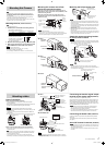
Connecting the power cable to AC 24 V source
(VN-H57U)
Conductor
diameter (mm)
1.0 mm dia
or more
1.6 mm dia
or more
2.0 mm dia
or more
Max cable
distance (meters)
(Reference value)
90 240 370
Note
• For safety reasons, turn on the power only after
confirming that all the connections are completed.
•
Be sure to turn off the camera before connecting cables.
•
If you use both the AC 24 V power cable and the PoE-
based LAN cable simultaneously, the camera may fail.
Always supply power using either method.
● LAN cable
When connecting to a switching hub:
Use a straight cable.
When connecting to a computer:
Use a crossing cable.
A 100-meter or less length and Category-5 or higher
grade STP (shielded) cable is recommended.
Note
•
The crossing cable may not be used for some computer
models. Check the LAN specifications of the computer
when you directly connect this unit to the computer.
Alarm I/O cable (VN-H57U)
A 50-meter or less length shielded cable is
recommended.
●
•
•
•
●
•
Connect the stereo mini jack cable (Φ 3.5).
R channel (MIC IN) : Connect to a condenser microphone that has a plug-in power system.
L channel (LINE OUT) : Connect to a speaker that has a built-in amp.
Note
• Always connect an external mic to the R channel only. If you plug the mic jack directly into the [AUDIO IN/OUT]
terminal, a loud noise may be generated.
Memo
• A shielded audio cable is recommended.
* For the location to connect the audio cable, refer to [Cabling] (
☞
page 2).
EN_VN-H57_001D_Non-Mask.indb 4EN_VN-H57_001D_Non-Mask.indb 4 5/24/2012 10:53:34 AM5/24/2012 10:53:34 AM


Find Your Products By Category
- Household Appliance
- Power Tools
- Computer Equipment
- Automotive
- TV and Video
- Outdoor Cooking
- Marine Equipment
- Kitchen Appliance
- Fitness & Sports
- Lawn and Garden
- Baby
- Laundry Appliance
- Personal Care
- Home Audio
- Photography
- Video Game
- Portable Media
- Musical Instruments & Equipment
- Communications
- Car Audio and Video
Please Login
