
0
Owner's of the JVC Security Camera VN-H137U gave it a score of 0 out of 5. Here's how the scores stacked up:
2
☞
Continued overleaf
Mounting this Camera
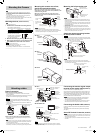
Mounting the lens (VN-H57U/VN-H37U)
Note
• Use a Megapixel lens only.
1 Check the lens mount before mounting the lens.
• The VN-H37U has the CS mount.
• The lens mount size (a) must be as shown in the table below.
Lens Flange focus (b) Dimension (a)
CS mount lens 12.5 mm 5.5 mm or less
•
Never use a lens whose dimension
(a) is more than the specified value.
Otherwise, the lens may not be
mounted correctly, or internal parts
of the camera may be damaged.
Also, the camera may fail.
Flange focus
(a)
(b)
2
Mount the lens securely by rotating it clockwise (CW).
3 When using a DC iris lens, connect the lens cable
to the IRIS terminal at the side of this camera.
Memo
• You cannot use a video iris lens.
• If the lens cable plug does not match, use a 4-pin plug.
[4-pin plug part number: SCV2859-001]
The 4-pin plug is available from the dealer or a JVC Service Center.
Note
• Special attention is required when installing the camera to the wall
or ceiling. You should not carry out installation work yourself. Ask a
professional to do the job, because injuries and accidents may occur if
the camera falls.
• To prevent this camera from falling, connect it to a strong section (a
ceiling slab or channel) using a fall prevention wire.
• When you attach the camera body to the ceiling, be sure to wear safety
goggles to protect your eyes from falling objects.
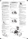
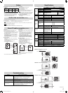
Mounting this camera onto a fixer,
pan/tilt unit and similar object
When you mount the camera onto a fixer, pan/tilt unit or
similar object, use the tripod screw hole (1/4-20UNC) of the
camera-mounting bracket.
When you mount the camera on a high place, fix the
fall-prevention wire to the wire attachment screw on the
camera rear panel.
Camera-
mounting
bracket
5 mm to
7 mm
1/4-20UNC
Screw hole for the camera-
mounting (1/4-20UNC)
Rotation-
preventive
hole
Camera-mounting
screws (x2: M2.6 x
8 mm)
Camera-mounting
bracket
Note
• Tighten setscrews securely.
• Use the screws to mount the camera so that the screws protrude
between 5 and 7 mm from the mounting surface. Do not use screws that
exceed the specified length as it may damage the internal parts.
Power Connection
When using the PoE cable (Common)
• Power is supplied via the LAN cable. Connect the PoE power
sourcing equipment.
• When power is supplied, the [STATUS] indicator lights up orange on
the side of this camera and lights up green after booting.
Memo
•
You can also turn the [STATUS] indication Off when the camera is
operating. For details about the settings, see “Instructions (Setting)” on the
supplied CD-ROM.
• A Category-5 or higher grade cable is recommended for 100BASE-TX
communication.
•
Be sure to properly ground the PoE power sourcing equipment before use.
PoE power sourcing
equipment
VN-H57U VN-H37U/VN-H137U
PoE power sourcing
equipment
When connecting the AC 24 V power cable (VN-H57U)
• When power is supplied, the [STATUS] indicator lights up on the
camera side panel.
Note
• Always use an AC 24 V power supply that is insulated from the primary
power circuit. An autotransformer or similar single-winding transformer
may fail or damage the camera.
•
If you use both the AC 24 V power cable and the PoE-based LAN cable
simultaneously, the camera may fail. Always supply power using either method.
Mounting the fall prevention wire
Fall prevention wire
(Prepared by customer)
Attachment screw for
fall prevention wire
(M3 x 6 mm)
6 mm
2 mm or less
Note
• Take note of the length, strength and pull of the fall prevention wire. For
the fall prevention wire use the insulation material. Make the wire length
as short as possible.
The wire must be sufficiently strong to hold the weight of the camera and
the total weight of the lens and fixer. (Also, make sure that the wire ends
are terminated carefully)
• Use the screws mounted on the camera rear panel to hold the fall
prevention wire.
• Mount the fall prevention wire using an attachment screw for the fall
prevention wire.
Use the screws (M3 x 6 mm) mounted on the rear panel of the camera to
hold the fall prevention wire. Do not use a screw that is longer than 6 mm
as doing so may damage the inside of the camera.
Attach the camera-mounting bracket
to the top of this camera
Memo
•
The bracket is attached to the bottom of this camera before being shipped
from the factory. Remove two screws for the camera-mounting bracket and
attach the bracket to the top of the camera if required.
Two (M2.6 x 8 mm) screws to secure
the camera-mounting bracket
[STATUS]
indicator
Two (M2.6 x 8 mm) screws to secure
the camera-mounting bracket
Camera-mounting
bracket
Camera-mounting bracket
Note
• Use setscrews with a length of 8 mm or less to secure the camera-
mounting bracket. Do not use screws that exceed the specified length as
it may damage the internal parts.
Screw hole for the camera-
mounting (1/4-20UNC)
Camera-mounting
bracket
Two (M2.6 x 8 mm) screws to secure
the camera-mounting bracket
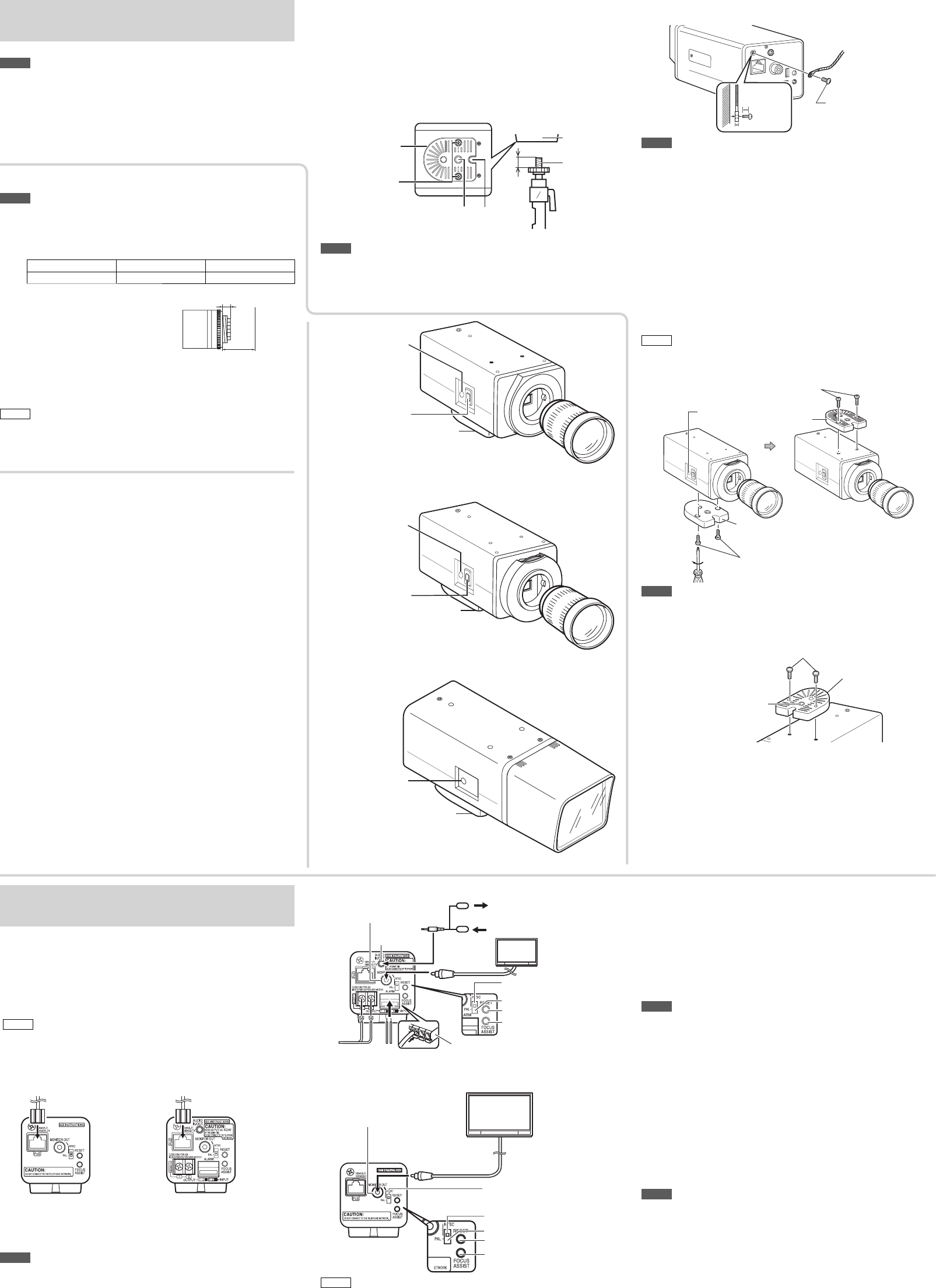
Attaching cables
VN-H37U
Camera-mounting
bracket
Iris terminal
[STATUS]
indicator
VN-H137U
Camera-mounting
bracket
[STATUS]
indicator
VN-H57U
To AC 24 V
power supply
Test monitor
* For field angle
adjustment
Speaker with integrated amp
Alarm cable
Plug-in power condenser
microphone
[MONITOR] terminal
[RESET] button
[FOCUS ASSIST] button
Cable stopper
PAL
[MONITOR] selection switch
NTSC
[AUDIO IN/
OUT] terminal
75 Ω
termination
VN-H37U/VN-H137U
75 Ω
termination
Test monitor
* For field angle
adjustment
[RESET] button
[FOCUS ASSIST] button
PAL
NTSC
[MONITOR] terminal
[MONITOR] selection switch
Memo
• The camera has the 16:9 aspect ratio. If the test monitor for checking
the image has the 4:3 aspect ratio, the camera image is converted and
displayed in the 4:3 ratio.
Connecting the monitor signal output
terminal to the coaxial cable
(Common)
Connect a test monitor to the [MONITOR] terminal.
Use this terminal to adjust the field angle during camera setup and to
adjust the focus in Focus Assist mode. Connect an RCA video cable
from this MONITOR terminal to the video monitor. When using a PAL
system monitor, set the [MONITOR] switch to the "PAL" position. Then,
press the RESET button to restart the camera.
Note
• If you extend the cable, more signals attenuate, the video resolution
drops, and video noise increases. A cable with lower attenuation is
recommended for when the camera is attached.
• If you keep pressing the [RESET] button for more than 5s, the camera
enters the Service mode. Do not press this button for more than 5s.
Connecting the Audio cable
(VN-H57U)
Connect the stereo mini jack cable to the [AUDIO IN/OUT] terminal
(Φ3.5 mm).
For details about the audio cable, refer to [Audio cable connection]
(
☞
page 4).
Alarm I/O Terminal Connection (VN-H57U)
Note
• An ambient noise source may cause a malfunction of the camera even if
the cable length is 50 meters or less. In that case, keep the noise source
away from the camera system.
• The cable stopper may drop from the Alarm terminal. Securely connect
the cables.
VN-H57U
Camera-mounting
bracket
Iris terminal
[STATUS]
indicator
EN_VN-H57_001D_Non-Mask.indb 2EN_VN-H57_001D_Non-Mask.indb 2 5/24/2012 10:53:33 AM5/24/2012 10:53:33 AM


Find Your Products By Category
- Household Appliance
- Power Tools
- Computer Equipment
- Automotive
- TV and Video
- Outdoor Cooking
- Marine Equipment
- Kitchen Appliance
- Fitness & Sports
- Lawn and Garden
- Baby
- Laundry Appliance
- Personal Care
- Home Audio
- Photography
- Video Game
- Portable Media
- Musical Instruments & Equipment
- Communications
- Car Audio and Video
Please Login
