

0
Owner's of the Honeywell Universal Remote Honeywell Universal Remote gave it a score of 0 out of 5. Here's how the scores stacked up:

SPYDER® BACNET® PROGRAMMABLE CONTROLLERS
63-2689—05 10
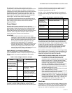
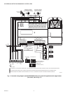
Cabling should be selected that meets or exceeds the BACnet
Standard which specifies the following: An MS/TP EIA-485
network shall use shielded, twisted-pair cable with
characteristic impedance between 100 and 130 ohms.
Distributed capacitance between conductors shall be less than
100 pF per meter (30 pF per foot). Distributed capacitance
between conductors and shield shall be less that 200 pF per
meter (60 pF per foot). Foil or braided shields are acceptable.
The Honeywell tested and recommended MS/TP cable is
Honeywell Cable 3322 (18 AWG, 1-Pair, Shielded, Plenum
cable), alternatively Honeywell Cable 3251 (22 AWG, 1-Pair,
Shielded, Plenum cable) is available and meets the BACnet
Standard requirements (www.honeywellcable.com).
The maximum BACnet MS/TP network Bus segment length is
4,000 ft. (1,219 m) using recommended wire. Repeaters must
be used when making runs longer than 4,000 ft. (1,219 m). A
maximum of three repeaters can be used between any two
devices.
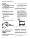
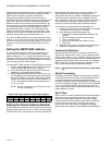
Setting the MS/TP MAC address
The MS/TP MAC address for each device must be set to a
unique value in the range of 0-127 on an MS/TP network
segment (address 0, 1, 2, & 3 should be avoided as they are
commonly used for the router, diagnostic tools, and as spare
addresses). DIP switches on the Spyder BACnet controller are
used to set the controller's MAC address.
To set the MS/TP MAC address of a Spyder BACnet controller:
1. Find an unused MAC address on the MS/TP network to
which the Spyder BACnet controller connects.
2. Locate the DIP switch bank on the Spyder BACnet for
addressing. This is labeled MAC Address
3. With the Spyder BACnet Controller powered down, set
the DIP switches for the MAC Address you want. Add the
value of DIP switches set to ON to determine the MAC
address. See Table 6. Example, if only DIP switches 1, 3,
5, and 7 are enabled the MAC address would be 85 (1 +
4 + 16 + 64 = 85).
NOTE: See Fig. 15 on page 12 for DIP switch orienta-
tion and arrangement.
Setting the Device Instance Number
The Device Instance Number must be unique across the entire
BACnet system network because it is used to uniquely identify
the BACnet devices. It may be used to conveniently identify the
BACnet device from other devices during installation. The
Spyder BACnet Controllers Device Instance Number is
automatically set when it is added to a WEBStation-AX project.
The Device Instance Number can be changed by the user,
which may be necessary when integrating with a third party or
when attempting to replace an existing controller and it is
desired to maintain the existing Device Instance Number.
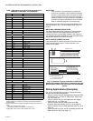
To edit the Device Instance Number using WEBs AX:
1. Identify an unused Device Instance Number on the BAC-
net Network, in the range of 0 - 4194302.
2. Open the Spyder Bacnet Device Mgr View
a. Double click on the BacnetNetwork located in the
Nav tree.
b. Select the Spyder Controller to be modified.
c. Click on the Edit button.
d. Enter an unused value in the Device Id field.
e. Select OK
3. Right Click on the Spyder Controller and select Actions >
Write Device Instance to complete the update
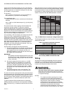
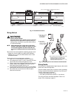
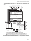
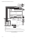
Termination Resistors
Matched terminating resistors are required at each end of a
segment bus wired across (+) and (-). Use matched precision
resistors rated 1/4W ±1% / 80 - 130 Ohms. Ideally, the value of
the terminating resistors should match the rated characteristic
impedance of the installed cable. For example, if the installed
MS/TP cable has a a listed characteristic impedance of 120
Ohm, install 120 Ohm matched precision resistors.
NOTE: The controller does not provide any network bias-
ing.
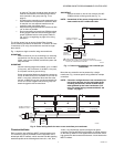
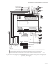
Shield Terminating
Following proper MS/TP cabling shield grounding procedures
is important to minimize the risk of communication problems
and equipment damage caused by capacitive coupling.
Capacitive coupling is caused by placing MS/TP cabling close
to lines carrying higher voltage. The shield should be grounded
on only one end of the MS/TP segment (typically the router
end). Tie the shield through using the SHLD (terminal 4) on the
Spyder BACnet Controller.
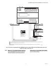
Sylk™ Bus
Sylk is a two wire, polarity insensitive bus that provides both 18
VDC power and communications between a Sylk-enabled
sensor and a Sylk-enabled controller. Using Sylk-enabled
sensors saves I/O on the controller and is faster and cheaper
to install since only two wires are needed and the bus is
polarity insensitive. Sylk sensors are configured using the
latest release of the Spyder Tool for WEBPro and WEBStation.
Table 6. DIP Switch Values For MS/TP MAC Address.
DIP 7654321
VALUE 6432168421


Find Your Products By Category
- Household Appliance
- Power Tools
- Computer Equipment
- Automotive
- TV and Video
- Outdoor Cooking
- Marine Equipment
- Kitchen Appliance
- Fitness & Sports
- Lawn and Garden
- Baby
- Laundry Appliance
- Personal Care
- Home Audio
- Photography
- Video Game
- Portable Media
- Musical Instruments & Equipment
- Communications
- Car Audio and Video
Please Login
