
0
Owner's of the Aiphone Stereo Receiver AXW-AVT gave it a score of 0 out of 5. Here's how the scores stacked up:
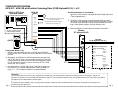
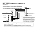
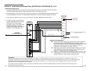
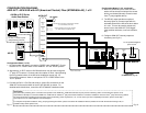
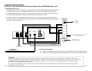
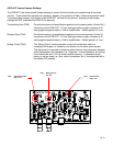
CONFIGURATION DIAGRAM:
AXW-AVT / AXW-AVR with AFI (American Fibertek) Fiber (MT/MR-89A-AX), 1 of 2
Pg. 11 Pg. 12
CCTV Camera
75 Ohm, 1V Peak-to-peak
(Independently powered)
Normally Closed input for remote activation
(i.e. motion sensor, loop detector, etc.)
Normally Open contact for remote device activation
(i.e. video switcher, DVR, etc.)
AXW-AVT
24V
+
-
RELAY
NO
NO
SENSOR
NC
NC
CALL IN
+
-
CALL OUT
+
-
AUDIO IN
+
-
AUDIO OUT
+
-
DOOR
VIDEO IN
VIDEO OUT
AX-DV
AX-DM or IE/IF-Series
Audio Door Station
CAT-5e
Coax
*
+
-
PS-2420UL
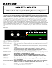
Please Note:
Only information pertaining to the connection and operation of the AXW-AVT / AXW-AVR and listed 3
rd
party devices interfacing with it are included here. Aiphone is not
responsible for attempts to connect the AXW-AVT / AXW-AVR to untested 3
rd
party transmission hardware. Consult the installation manual for the 3
rd
party device being utilized
for further information regarding physical mounting, base functionality, power requirements, etc. For the most up-to-date compatibility information, please consult http://
www.aiphone.com or contact Aiphone Technical Support.
For complete AX system installation, wiring, and programming information, please consult the AX Installation Manual (included on CD with AX Central Exchange Unit, or
available at http://www.aiphone.com).
Optic Fiber
(to MR-89A-AX, Pg. 13)
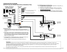
Configuration Notes (1 of 2):
1. AX-series video door station connects to ‘DOOR’ input of AXW-AVT. Ensure
that the “CCTV / DOOR’ switch on the AXW-AVT is in the ‘DOOR’ position.
*2. Alternatively, an IE/IF-series or AX-DM audio door may be used, along with
3
rd
party CCTV camera. Connect audio door station to ‘Door’ input (following
the wiring method shown in the AX-series installation manual, pg. 12).
Connect the camera to ‘Video In’ and put the ‘CCTV / DOOR’ switch in the
‘CCTV’ position.
3. Connect the Call In / Call Out and Audio In / Audio Out connections on the
AXW-AVT to the terminal block of the AFI MT-89A-AX, as shown. For
detailed terminal definitions, consult the AFI MT-89A-AX installation sheet.
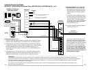
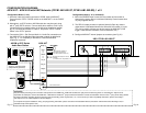
Configuration Notes (1 of 2, continued):
4. When the SENSOR input is used, the door
station will be turned on whenever the sensor
device is activated (Normally Closed contact
from 3
rd
party supplied device).
5. The RELAY output provides an optional
Normally Open dry contact output which is
activated whenever the AX-series door station
is in use. This can be used to activate any
device local to the AXW-AVT (DVR trigger,
video switcher activation, local call indication,
etc.).
6. Configure AXW-AVT internal jumpers as
necessary (see Pg. 21).
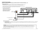
Coaxial Video Cable
AFI MT-89A-AX
To AFI specified/supplied
power source
12VDC
+
-
+
-
+
-
+
-
Door Release/
Contact Out (optional)
AudioContactContact
Video
IN
Optical
I/O


Find Your Products By Category
- Household Appliance
- Power Tools
- Computer Equipment
- Automotive
- TV and Video
- Outdoor Cooking
- Marine Equipment
- Kitchen Appliance
- Fitness & Sports
- Lawn and Garden
- Baby
- Laundry Appliance
- Personal Care
- Home Audio
- Photography
- Video Game
- Portable Media
- Musical Instruments & Equipment
- Communications
- Car Audio and Video
Please Login
