
0
Owner's of the Aiphone Intercom System Aiphone Intercom System gave it a score of 0 out of 5. Here's how the scores stacked up:

Pg. 2
IS-DVF-2RA Instr.
0411JD
Aiphone Corporation
1700 130th AVE NE * Bellevue, WA 98005
Ph: (800) 692-0200 * Fax: (425) 455-0071
tech@aiphone.com
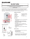
WIRING DIAGRAM:
IS-DVF-2RA
IS-CCU
IS-MV
IS-PU-UL
N/O Dry Contact
0.5 Amp
CAT-5e
CAT-5e
NO
COM
NC
FCC WARNING:
This device complies with Part 15 of the FCC rules.
Operation is subject to the following two conditions:
(1) This device may not cause harmful interference.
(2) This device must accept any interference that may cause undesired operation.
• For proper regulatory compliance, the drain wire should be disconnected at the power
supply end of the cable.
• Changes or modications not expressly approved by the party responsible for
compliance could void the user’s authority to operate the equipment.
TOLL FREE TECHNICAL SUPPORT:
(800) 692-0200
E-MAIL: tech@aiphone.com
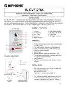
SPECIFICATIONS:
Camera unit: CMOS camera
Scanning line: 525 lines
Min. illumination: 5 Lux at 1’6”
Terminations: RJ45 jack for audio/video
Screw terminals for door release and relay outputs
Relay rating: 24V AC/DC 0.5A on Door station, 24V AC/DC 1.0A on relay board
Operating Temp: 14° ~ 140°F / -10° ~ 60°C
Wiring Distance: 980’ with Cat5e/6 cable
Dimensions: 11-3/4” H x 7” W
w/SBX-ISDVFRA: 11-11/16” H x 7-1/16” W x 2-13/16” D (top), 1-13/16” D (bottom)
OFF ON
NO
NO
C
NC
C
NC
1 2 3 4
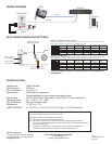
RELAY BOARD WIRING AND SETTINGS:
Relay 1 Output
N/O, COM, N/C
Relay 2 Output
N/O, COM, N/C
*Relay 2 External Reset
Connect to N/O dry switch
Conguration Switch
See Settings to right
OFFON
NO
NO
C
NC
C
NC
1234
Board on back of unit
See wiring below
ON
1 2 3 4
Default Conguration when shipped
Optional Conguration
Normal Call
Emergency Call
Talking
Door Release
Trigger Source RY1 Triggered?
RY1 Remains ON
During Talking?
RY2 Triggered?
RY2 Remains ON
During Talking?
RY2 Requires
Reset?
YES
NO N/A
YES
YES YES
YES YES NO
NO
NO
NO
N/A
N/A
N/A
N/A
N/A
N/A
YES
YES
ON
1 2 3 4
Contact Technical Support if additional switch congurations
are required.
Relay 1 triggers on normal call, emergency call, and communication. Relay 1 remains on during communication.
Relay 2 triggers on emergency call and remains on during communication.
Relay 1 triggers on normal call, emergency call, and communication. Relay 1 remains on during communication.
Relay 2 triggers on an emergency call and remains on during communication. Relay 2 requires reset.
Normal Call
Emergency Call
Talking
Door Release
Trigger Source RY1 Triggered?
RY1 Remains ON
During Talking?
RY2 Triggered?
RY2 Remains ON
During Talking?
RY2 Requires
Reset?
YES
NO N/A
YES
NO N/A
N/A
N/A
YES
YES
YES
YES
YES YES
N/A
N/A
N/A
NO
NO
YES*


Find Your Products By Category
- Household Appliance
- Power Tools
- Computer Equipment
- Automotive
- TV and Video
- Outdoor Cooking
- Marine Equipment
- Kitchen Appliance
- Fitness & Sports
- Lawn and Garden
- Baby
- Laundry Appliance
- Personal Care
- Home Audio
- Photography
- Video Game
- Portable Media
- Musical Instruments & Equipment
- Communications
- Car Audio and Video
Please Login
