
0
Owner's of the 3M Life Jacket Powered Infeed Conveyor gave it a score of 0 out of 5. Here's how the scores stacked up:

18
7-INSTALLATION AND OPERATION (continued)
2011 June
a80f-if-NA
7.4 Preliminary Electric Inspection
Before connecting the machine to the mains please
carry out the following operations:
7.4.1 Make sure that the socket is provided with
an earth protection circuit and that both the
mains voltage and the frequency match
the specifi cations on the name plate.
7.4.2 Check that the connection of the machine
to the mains meets the safety regulations in
your country.
7.5 Machine Connection to the Mains
For technical specifi cations:
See Section 4 - Specifi cations
- Push the
LATCHING EMERGENCY STOP BUTTON.
- The main switch is normally turned OFF.
Connect the power cord supplied with the machine
to a wall socket using a plug which complies with the
safety regulations of your country.
7.4.3 The machine is fi tted with a main switch.
The user will be responsible for testing the
short-circuit current in its facility and should
check that the short-circuit amperage setting
of the machine is compatible with all the
components of the mains system.
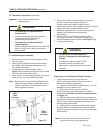
• To reduce the risk associated with
mechanical and electrical hazards:
− Read, understand, and follow all safety
and operating instructions before operating
or servicing the Infeed Conveyor/Case Sealer.
• To reduce the risk associated with
hazardous voltage:
− Position electrical cord away from foot
and vehicle traffi c.
WARNING
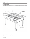
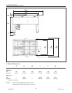
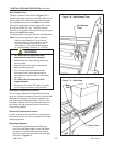
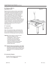
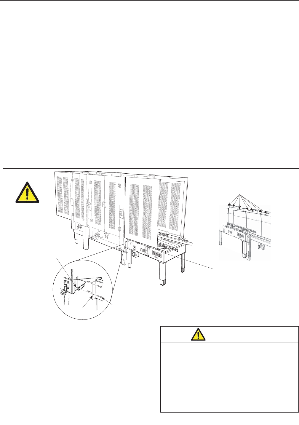
Production Line Installation
Refer to Figure 7-4 for installation Setup. Infeed
convey-or bed must be level and equal to case sealer
bed height. Secure infeed conveyor mounting brack-
ets to infeed conveyor and case sealer as shown.
Plug the air line from the infeed conveyor into the
designated port on the case sealer as shown
(Figure 7-5).
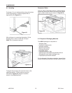
7.6 Pneumatic Connection
The infeed conveyor requires a 5.2 bar gauge pres-
sure [75 PSIG], 28 litre/min @ 21°C, 1.01 bar
[1.0 SCFM] compressed air supply.
Remove all packaging materials and tools from the
conveyor before connecting the air line to energize
the pneumatic components.
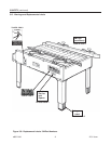
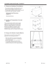
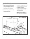
Front and Rear Flaps
must be inside side Flaps
Electrical Connection:
The electrical control box, shown in Figure 7-5, contains
the "On/Off" switch with pre-set circuit breaker.
A power supply cord extends from the bottom of the
electrical control box (switch). Plug this cord into the
receptacle on the lower left side (infeed end) of the
a80f-if case sealer frame as shown in Figure 2-4.
Figure 7-4
Infeed Conveyor must
be level and equal to
Case Sealer Bed
Height
ELE
C
TRI
C
Flat
Head
Screw
Socket
Head
Screw
Bracket
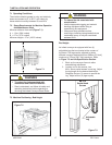
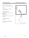
Important! Use care when working with
compressed air.


Find Your Products By Category
- Household Appliance
- Power Tools
- Computer Equipment
- Automotive
- TV and Video
- Outdoor Cooking
- Marine Equipment
- Kitchen Appliance
- Fitness & Sports
- Lawn and Garden
- Baby
- Laundry Appliance
- Personal Care
- Home Audio
- Photography
- Video Game
- Portable Media
- Musical Instruments & Equipment
- Communications
- Car Audio and Video
Please Login
