
0
Owner's of the Tripp Lite TV Cables B126-004 gave it a score of 0 out of 5. Here's how the scores stacked up:
9
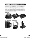
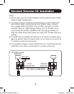
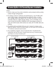
Standard Extender Kit Installation
1
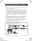
Make sure the HDMI source is powered OFF.
2
ConnecttheHDMIsourcetotheINPUTportontheB126-1A1or
B126-1A1-WPlocalunitusingaTrippLiteP568-SeriesHDMICable.
3
Optional for B126-1A1: Connect a local monitor to the LOCAL port
ontheB126-1A1localunitusingaTrippLiteP568-SeriesHDMI
Cable.
4
Connect the external power supply to the local unit and plug it into
a Tripp Lite Surge Suppressor, Power Distribution Unit (PDU) or
Uninterruptible Power Supply (UPS). The green LED illuminates to
indicate the unit is receiving power from the external power supply.
5
UsingCat5e/6cable,connecttheRJ45portonthelocalunittothe
RJ45portontheremoteunit.
6
Connect the external power supply to the remote unit and plug it
into a Tripp Lite Surge Suppressor, PDU or UPS. The green LED
illuminates to indicate the unit is receiving power from the external
power supply. The orange LED illuminates to indicate the unit is
connectedtoapoweredONlocalunit.
7
Connect the remote unit’s HDMI port to a monitor using a Tripp Lite
P568-SeriesHDMICable.
8
Turn on the power to the HDMI source. The orange LED on the
local unit illuminates to indicate a signal is being received from the
source.
9
If necessary, use the Equalization control on the remote unit to
adjust the video image. Note: An improper Equalization setting
can cause the monitor not to display a picture at all. Try each
Equalization setting until an acceptable picture is displayed.
201109206-93-3023-EN.indd 9 10/24/2011 10:01:20 AM


Find Your Products By Category
- Household Appliance
- Power Tools
- Computer Equipment
- Automotive
- TV and Video
- Outdoor Cooking
- Marine Equipment
- Kitchen Appliance
- Fitness & Sports
- Lawn and Garden
- Baby
- Laundry Appliance
- Personal Care
- Home Audio
- Photography
- Video Game
- Portable Media
- Musical Instruments & Equipment
- Communications
- Car Audio and Video
Please Login
